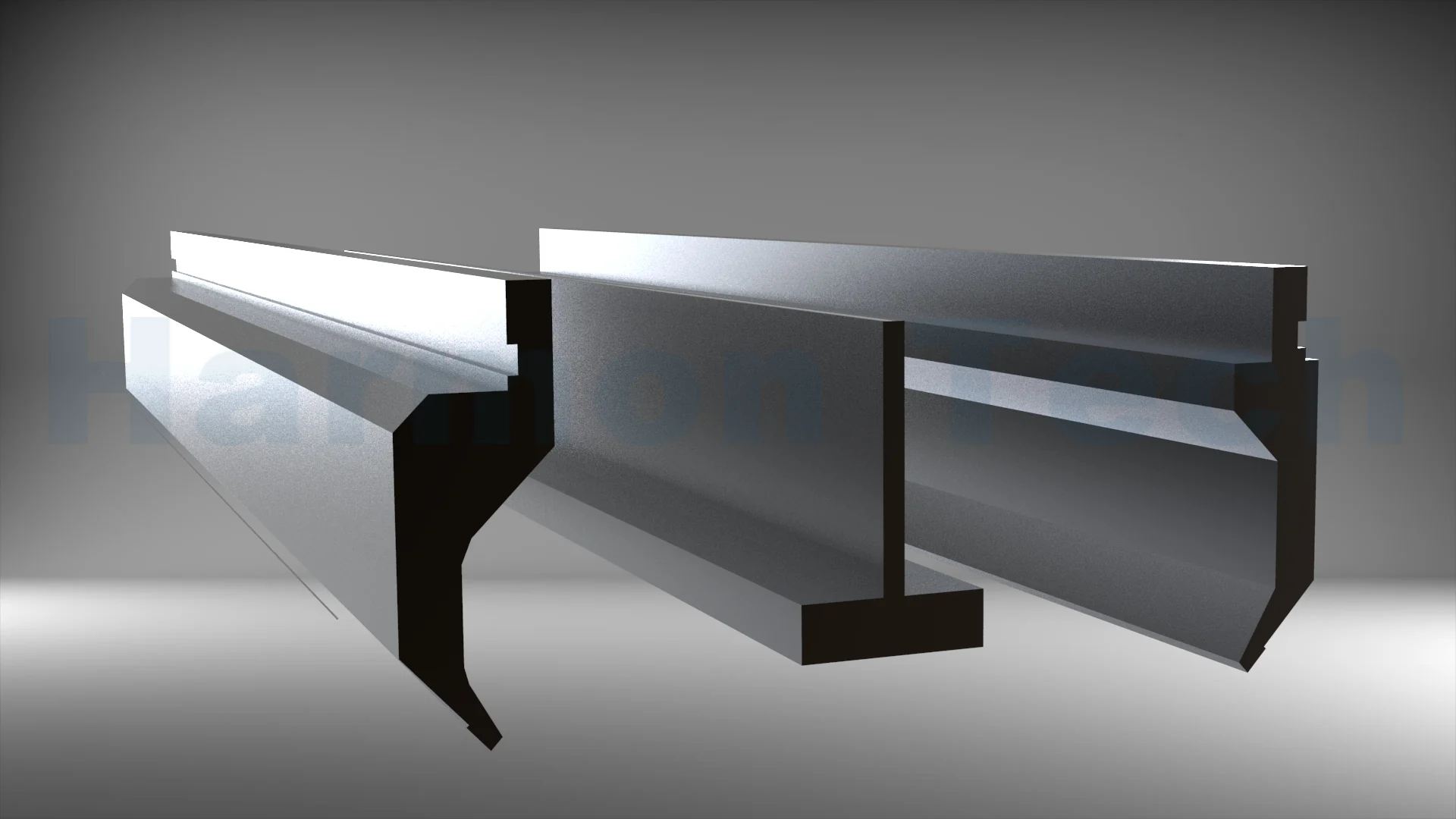
How to Choose Press Brake Tooling: A Practical Punch and Die Selection Guide
Choosing press brake tooling is not simply a matter of matching a punch and die to sheet thickness. The selected combination must produce the required angle and inside radius, support the shortest flange, remain within the allowable load of the tool and machine, clear the finished part, and fit the press brake’s clamping system.
That makes tooling selection a sequence, not a catalog choice. Start with the drawing and material. Decide how the bend will be formed. Establish a practical V-opening. Then select the punch profile and verify force, capacity, interface, working height, and segmentation.
This guide explains that sequence for common air-bending work and shows where manufacturer data must replace general rules of thumb.
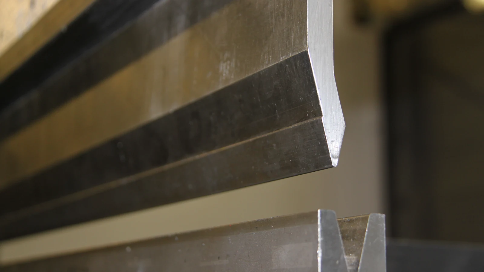
Start With the Part, Material, and Bending Method
Before looking at tooling profiles, collect the inputs that control the bend:
– Material grade and condition
– Material thickness and tolerance
– Bend length
– Required bend angle
– Target inside bend radius
– Minimum flange length
– Grain direction, if controlled
– Surface-finish or marking limits
– Part geometry around the bend
– Annual volume and expected tool life
– Press brake model, tonnage, stroke, open height, and clamping system
The material grade matters because strength influences required bending force and springback. Two sheets with the same nominal thickness can behave differently if their tensile strengths, temper conditions, or thickness tolerances differ. Never approve a high-strength-steel application from a mild-steel rule alone.
Next, identify the forming method. Air bending is flexible because ram depth controls the final angle and one tool set can produce several angles. Bottom bending forms the sheet deeper into the die and requires a closer relationship among punch, die, angle, and material. Coining uses much higher pressure and must not be treated as an ordinary air-bending job.
For most mixed-production shops, air bending is the logical starting point. The remaining sections therefore use air-bending relationships unless stated otherwise.
Choose the V-Die Opening Before Finalizing the Punch
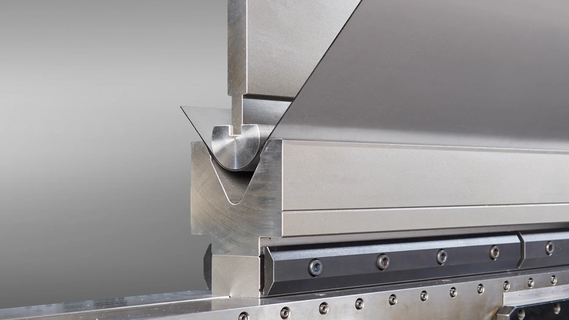
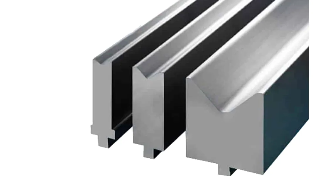
The V-opening influences three critical results at the same time: the naturally formed inside radius, the minimum flange the die can support, and the bending force. A narrow opening generally creates a smaller radius and supports a shorter flange, but it also increases force. A wider opening reduces force but produces a larger radius and requires a longer flange.
For common mild-steel air bending, the “rule of eight” uses a V-opening of approximately eight times material thickness as a starting point. Bystronic’s press brake tool-selection guidance also relates the naturally formed inside radius to roughly 16% of the V-opening and the minimum flange to roughly 77% of the V-opening under the stated conditions.
These relationships are screening tools, not universal specifications. A different material, target radius, forming method, die geometry, or short-flange requirement can change the answer. Use this decision sequence:
1. Calculate an initial V-opening from the material and method.
2. Estimate the natural inside radius for that opening.
3. Compare the estimated minimum flange with the drawing.
4. Check required force per unit length and total bend force.
5. Adjust the opening only after reviewing all four effects.
If the flange is too short for the candidate die, selecting a smaller opening may help, but it raises the required force. A specialized die, rotary die, urethane solution, or process change may be more appropriate than forcing the part into an unsuitable standard V-die.
Select the Punch Angle, Tip Radius, and Profile
After establishing a practical die opening, choose a punch that can create the bend without damaging the material or colliding with the part.
Punch angle
The punch and die angles must provide enough clearance to compensate for material springback and reach the required final angle. The best included angle depends on the material, forming method, and target bend. Do not assume that a sharper tool automatically produces a more accurate result.
Punch tip radius
In air bending, the V-opening and material behavior strongly influence the naturally formed inside radius. The punch tip should support the intended geometry without trying to force a radius smaller than the material can safely accept. If the drawing requires a larger controlled radius, a radius punch or another forming strategy may be needed.
An excessively sharp punch can concentrate stress, increase marking, and raise the risk of cracking in less ductile materials. A tip radius that is too large can prevent the tool from reaching the requested geometry. Confirm the relationship among punch radius, material ductility, grain direction, and target inside radius.
Punch profile and part clearance
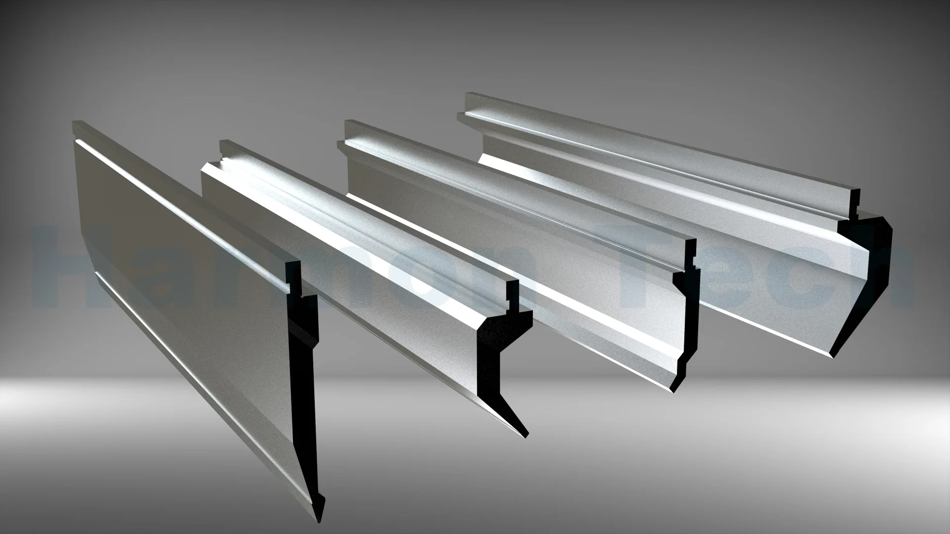
A straight punch suits many open bends. A gooseneck punch provides clearance for return flanges, boxes, channels, and previously formed bends. Evaluate the profile against the complete bend sequence, not just one cross-section. A tool that forms the first bend successfully may collide with the part during a later bend.
Use the CAD profile of the punch, die, holder, and part whenever possible. Check every bend step and include part rotation, gauging access, and removal clearance.
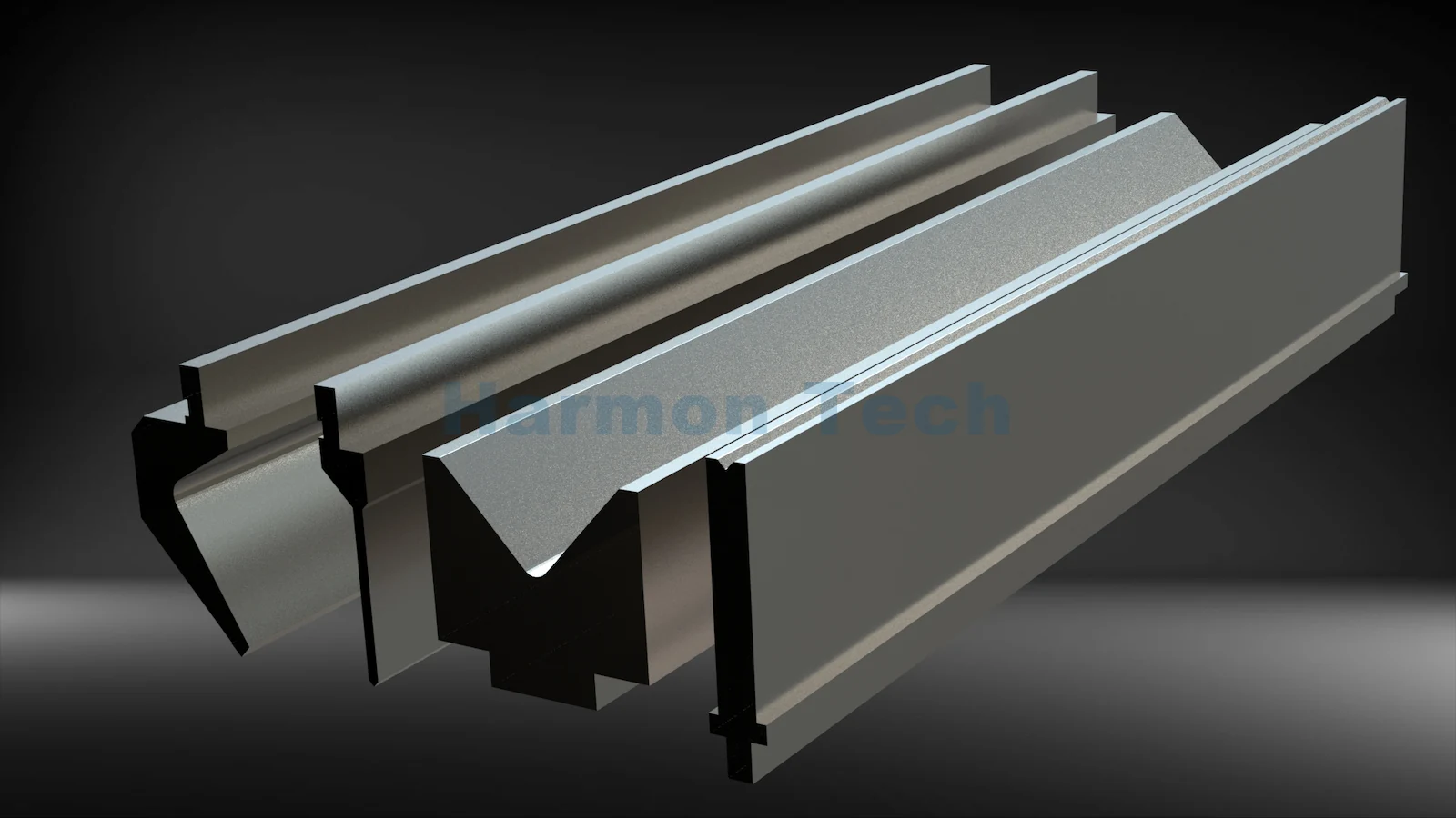
CAMT supplies multiple CAMT press brake tools for standard and application-specific bending. The correct family should still be selected from the part geometry and verified interface data rather than from appearance alone.
Check Tonnage Against Both the Tool and the Press Brake
A workable punch and die geometry is not automatically a safe setup. Required bending force must remain within every relevant load limit:
– The press brake’s available force for the actual bend position and length
– The punch’s allowable load per unit length
– The die’s allowable load per unit length
– The holder, adapter, and clamping-system ratings
– Any limit created by short segments or concentrated loading
Use a manufacturer-approved bending chart or calculator for the material, thickness, V-opening, and bend length. The Wilson Tool air-bend force chart is an example of the type of reference used for preliminary selection, but the final value must match the actual material and tooling system.
Keep units consistent. A chart may state force per metre, per foot, or for a defined bend length. Convert the chart value to the actual bend length before comparing it with machine tonnage. Then check the tool rating in its stated units and for the installed segment length.
Short parts require special attention. Total force may appear modest while the load is concentrated into a small area. Do not place a short, highly loaded segment where the machine or tool manufacturer prohibits concentrated loading. A higher-capacity press does not make a low-capacity tool safe.
The Cincinnati press brake tooling considerations sheet provides a concise verification framework: bending method, V-opening, radius, minimum flange, required tonnage, tooling load capacity, machine capacity, die space, and clamping all need to agree.
Verify Tooling-System and Machine Compatibility
“European,” “Promecam,” “WILA/New Standard,” “Amada style,” and “American style” are useful system labels, but a label alone does not prove interchangeability. Confirm actual dimensions and operating requirements.
Check the following before ordering:
– Punch tang or die base profile
– Clamping and safety-retention geometry
– Tool centerline and seating surfaces
– Tooling and holder working height
– Machine stroke, open height, and available daylight
– Maximum tool height and die width
– Adapter requirements
– Segmentation lengths and horn pieces
– Crowning compatibility
– Whether the setup permits front loading, vertical loading, or both
Working height affects whether the press brake can open far enough to load, rotate, and remove the part while retaining enough stroke to complete the bend. Interface mismatch can also create alignment error or prevent safe retention. Never grind or modify a tang to “make it fit” without written engineering approval.
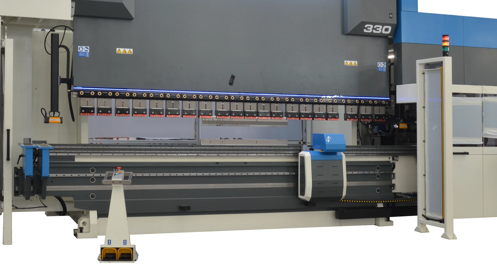
Review press brake clamping system options when planning a tooling family or retrofit. Send CAMT the machine model, photographs or drawings of the current clamp and holder, critical interface dimensions, and required working height.
Account for Surface Finish, Tool Material, and Heat Treatment
Tooling selection also affects the visible surface of the part and the service life of the tool.
Polished stainless steel, pre-painted sheet, aluminum, and coated material may need wider die-shoulder radii, clean contact surfaces, protective film, a non-marking layer, or a specialized die solution. Any protective material placed between the sheet and die changes contact conditions and may influence bend consistency, so validate it by trial bending.
Tool steel, heat treatment, and surface treatment influence wear resistance, toughness, galling, and repairability. However, these properties cannot be judged from color or a generic product label. Ask the supplier for documented material, heat-treatment process, hardness range, hardened depth where relevant, straightness and profile tolerances, and rated load for the exact tool.
Do not select the highest advertised hardness in isolation. A tool must balance wear resistance with adequate toughness for its geometry and application. Thin sections, sharp transitions, special profiles, and high localized loads can require a different balance from a general-purpose straight punch.
Worked Example: Tooling for 3 mm Mild Steel
Consider a preliminary selection for the following part:
– Material: common mild steel, exact grade and tensile strength to be confirmed
– Thickness: 3 mm
– Bend length: 1,000 mm
– Method: 90-degree air bend
– Target inside radius: approximately 4 mm
– Minimum flange: 25 mm
– Surface: non-cosmetic
Step 1: Establish a candidate V-opening
Using the rule of eight as a mild-steel air-bending starting point:
V = 8 × 3 mm = 24 mm
Step 2: Screen the expected inside radius
Using an approximate natural radius of 16% of the V-opening:
Inside radius ≈ 0.16 × 24 mm = 3.84 mm**
That is close to the nominal 4 mm target, so the 24 mm opening remains a reasonable candidate. Check this estimate against the actual grade, grain direction, tooling geometry, and trial result.
Step 3: Screen the minimum flange
Using an approximate minimum flange of 77% of the V-opening:
Minimum flange ≈ 0.77 × 24 mm = 18.48 mm
The specified 25 mm flange is longer than this preliminary value, so the die appears able to support it. The real die-shoulder geometry and drawing tolerances still need confirmation.
Step 4: Select a punch candidate
Choose a punch angle that allows for expected springback and a tip radius compatible with the natural bend radius and material ductility. Select a straight or gooseneck profile only after checking the complete bend sequence for collision.
Step 5: Verify force and capacity
This example intentionally does not invent a tonnage figure. Look up the force for 3 mm material, the confirmed tensile strength, a 24 mm V-opening, and a 1,000 mm bend in the approved chart. Compare that result with press brake capacity and with the punch, die, holder, adapter, and clamp ratings.
Step 6: Confirm interface and prove the setup
Confirm tang profile, die base, working height, stroke, open height, segmentation, and retention. Run a controlled trial bend, measure the angle and radius, inspect the surface, and record the successful setup.
Diagnose Common Tooling Selection Failures
The bend angle varies along the part
Possible mechanisms include thickness variation, material-property variation, machine deflection, poor crowning compensation, worn tooling, incorrect seating, or misalignment. Verify material consistency and tool condition, then check seating, alignment, crowning, and measured angle along the bend.
The inside radius is too large
The V-opening may be wider than the application requires, the material may be stronger than assumed, or the requested radius may conflict with natural air-bending behavior. Confirm the opening and material, then evaluate a narrower safe die or a different forming method. Recalculate force before changing the die.
The flange falls into the die
The flange is below the support requirement for the selected opening or the part is positioned incorrectly. Compare the actual flange with the die geometry. A smaller opening, a special die, or a revised process may be required.
The surface is marked
Inspect die shoulders for contamination, wear, pickup, and sharp transitions. Confirm material orientation and contact pressure. Consider a larger shoulder radius, protective film, non-marking material, or application-specific tooling, then validate bend consistency.
The punch collides with a return flange
The profile or bend sequence does not provide enough relief. Model every forming step and consider a gooseneck or custom punch. Do not reduce the punch section without recalculating its load capacity.
Required force is unexpectedly high
Check whether the V-opening is too narrow, strength or thickness is higher than entered, bend length or units are wrong, or the process is bottoming instead of air bending. Stop the setup if any machine or tooling limit may be exceeded.
Decide Between Standard and Custom Tooling
Standard tooling is usually the first choice for common angles, radii, open bends, and repeatable production. It is easier to replace, segment, and reuse across multiple jobs. A well-planned standard library can cover a large share of a shop’s work.
Custom tooling becomes appropriate when the part requires an unusual radius or channel, multiple bends in one stroke, special clearance, controlled forming of an extrusion, mark-sensitive contact, or cycle-time reduction that standard tools cannot achieve.
Evaluate a custom tool on more than purchase price:
– Expected annual volume and tool life
– Setup and cycle-time savings
– Part consistency and inspection requirements
– Load distribution and weak cross-sections
– Repair, regrinding, and replacement strategy
– Storage, handling, and identification
– Whether a standard-tool process change could achieve the same result
For either path, require an approved drawing and documented load rating before production.
What to Send a Tooling Supplier
A useful tooling request should include enough information to reproduce the engineering problem. Send:
– A dimensioned part drawing and, if possible, a 3D model
– Material specification, grade, condition, thickness, and tolerance
– Bend angles, inside radii, flange lengths, and bend lengths
– Critical dimensions and acceptable angular variation
– Annual quantity and batch size
– Surface-finish and marking requirements
– Planned bending method
– Press brake manufacturer, model, tonnage, stroke, and open height
– Clamping and holder drawings or measured interface dimensions
– Current tooling system and adapter information
– Preferred segmentation and any horn requirements
– Photographs of the machine interface and similar finished parts
If a supplier receives only “3 mm steel for a 100-ton press,” it cannot reliably assess radius, flange, collision, interface, or tool capacity. More complete inputs lead to a more useful quotation and fewer changes during commissioning.
Final Press Brake Tooling Selection Checklist
Before releasing a setup, confirm that:
– The exact material and thickness are known.
– The forming method is defined.
– The V-opening supports the target radius and minimum flange.
– The punch angle, tip radius, and profile fit the bend and clear the part.
– Required force comes from an approved chart or calculation.
– The press brake, punch, die, holder, adapter, and clamp all remain within their ratings.
– Tang profile, die base, working height, stroke, open height, centerline, and retention are compatible.
– Segmentation and concentrated loads are acceptable.
– Surface-protection requirements are addressed.
– A trial bend and inspection plan are defined.
The safest and most repeatable tooling decision is the one that can be traced back to the drawing, material data, approved load information, interface dimensions, and a controlled trial.
For a CAMT tooling recommendation, send Harmon Tech your part drawing, material specification, bend requirements, machine model, clamping-system details, and preferred segmentation. CAMT can then review the application against an identified tooling configuration instead of relying on a generic thickness rule.
11. FAQ
1. What is the first step in choosing press brake tooling?
Start with the part drawing and confirmed material data. Record material grade, thickness, bend length, target angle, inside radius, minimum flange, surface requirement, and full bend sequence. Only then should you shortlist a V-die and punch.
2. How do I choose the correct V-opening for a press brake?
For air bending common mild steel, approximately eight times material thickness is a frequent starting point. Then verify the resulting inside radius, minimum flange, and bending force. Use the tooling manufacturer’s chart for the actual material and die geometry before approving the setup.
3. Does the punch radius determine the inside bend radius?
Not by itself. In air bending, V-opening, material properties, and thickness strongly influence the naturally formed radius. The punch tip must be compatible with that radius and material ductility. Bottoming, coining, and large-radius forming behave differently.
4. Are WILA, European/Promecam, and Amada-style tools interchangeable?
Do not assume they are. Verify tang or base geometry, seating surfaces, safety retention, centerline, working height, holder or adapter, and loading method from dimensioned drawings. Similar naming does not guarantee a safe fit.
5. How should I check press brake tooling tonnage?
Use an approved chart or calculator for actual material strength, thickness, V-opening, and bend length. Keep units consistent, then compare the result with machine, punch, die, holder, adapter, and clamp ratings. Include restrictions for short segments and concentrated loads.
6. When should I use a gooseneck punch?
Use a gooseneck profile when a straight punch would collide with a return flange, box wall, channel, or previous bend. Model the complete bend sequence and verify that the relieved profile still has adequate rated load.
7. What information does a press brake tooling supplier need?
Send the part drawing, material specification, thickness, angles, radii, flange and bend lengths, quantity, surface requirements, machine model, tonnage, stroke, open height, clamping interface, current holders or adapters, and desired segmentation.