Press Brake V Die Opening Chart: Metric and Inch Guide
A press brake V die opening chart gives you a starting V-width from the material thickness, but it does not make the final tooling decision. For ordinary mild-steel air bending, **V = 8 × material thickness** is a common baseline. The selected opening must then pass four checks: target inside radius, minimum flange, required bending force, and the rated capacity of the tool and press brake.
Use the charts below for preliminary selection only. Confirm the exact material strength, bend method, available die size, tool load rating, and machine capacity before production.
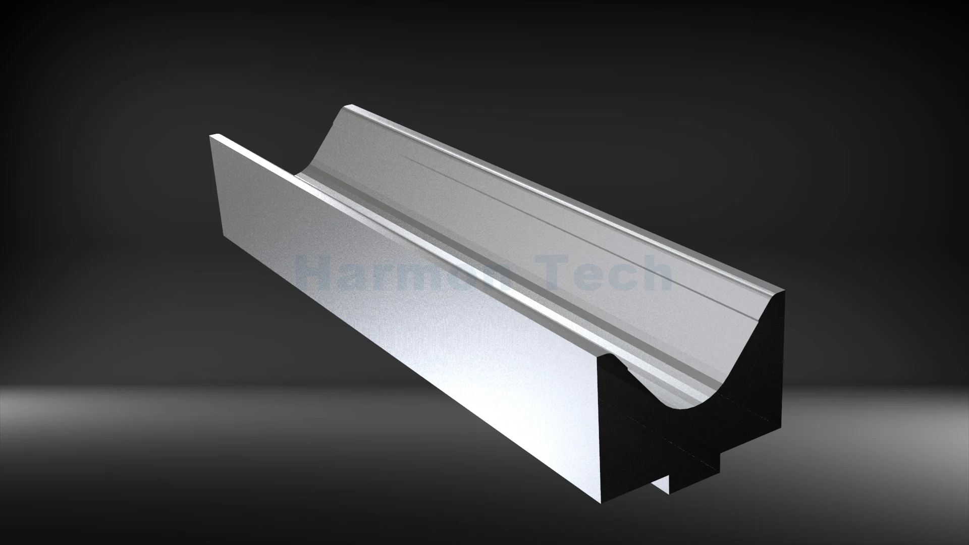
Quick Answer: How to Choose a V-Die Opening
For a 90-degree air bend in ordinary mild steel:
1. Start with a V-opening near eight times material thickness.
2. Use a smaller ratio only when a shorter flange or tighter natural radius is required and the higher force is acceptable.
3. Use a larger ratio when a larger inside radius is acceptable and lower force is preferred.
4. Check the flange against both die shoulders.
5. Calculate force for the actual material and bend length.
6. Verify the punch, die, holder, clamp, and machine ratings.
Quick-reference starting values for air bending—not machine setup authorization.
A ratio is written as a multiple of thickness. If the sheet is 3 mm thick, 8t means a 24 mm theoretical V-opening. The nearest available standard die may be V25, so every dependent value must be recalculated from the actual opening.
Manufacturer-Based Thickness Ratio Guide
A single multiplier is not appropriate for every thickness. Wilson Tool’s air bending force chart uses the following segmented starting relationships for 60,000 psi mild steel and an 88-degree included die angle. Wilson also labels the chart as reference information, so use the latest chart supplied with the actual tooling.
| Material thickness | Starting V-opening ratio | Practical meaning |
|---|---|---|
| Up to 2.6 mm | About 6t | Thin sheet often uses a narrower opening |
| 3–8 mm | About 8t | Common mild-steel air-bending baseline |
| 9–12 mm | About 10t | Wider opening reduces the rapidly increasing force |
| 14 mm and above | About 12t | Thick plate needs a broader starting point and full engineering review |
WILA’s guidance on V-opening size also emphasizes that the correct ratio changes with thickness, strength, desired radius, minimum leg length, and bend angle. Thin ordinary steel may start around 6–8t, while high-strength applications can require substantially wider openings.
These ranges explain why “always use 8t” is too simple. Use 8t as a familiar reference, then use the specific manufacturer chart for the job.
Metric Press Brake V Die Opening Chart
The table below compares four theoretical openings. It does not prescribe which opening is safe. Choose the ratio from material, radius, flange, and force requirements, then select the nearest available die and recalculate.
| Thickness t (mm) | 6t opening (mm) | 8t opening (mm) | 10t opening (mm) | 12t opening (mm) |
|---|---|---|---|---|
| 0.5 | 3.0 | 4.0 | 5.0 | 6.0 |
| 0.8 | 4.8 | 6.4 | 8.0 | 9.6 |
| 1.0 | 6.0 | 8.0 | 10.0 | 12.0 |
| 1.2 | 7.2 | 9.6 | 12.0 | 14.4 |
| 1.5 | 9.0 | 12.0 | 15.0 | 18.0 |
| 2.0 | 12.0 | 16.0 | 20.0 | 24.0 |
| 2.5 | 15.0 | 20.0 | 25.0 | 30.0 |
| 3.0 | 18.0 | 24.0 | 30.0 | 36.0 |
| 4.0 | 24.0 | 32.0 | 40.0 | 48.0 |
| 5.0 | 30.0 | 40.0 | 50.0 | 60.0 |
| 6.0 | 36.0 | 48.0 | 60.0 | 72.0 |
| 8.0 | 48.0 | 64.0 | 80.0 | 96.0 |
| 10.0 | 60.0 | 80.0 | 100.0 | 120.0 |
| 12.0 | 72.0 | 96.0 | 120.0 | 144.0 |
Mild-steel 8t baseline: radius and flange screening
For ordinary mild-steel air bending, Bystronic’s rules of press brake tool selection give two useful screening relationships:
– Estimated natural inside radius ≈ 0.16 × V
– Estimated minimum flange ≈ 0.77 × V
The following values are calculated from those relationships, not copied from a production load chart.
| Thickness (mm) | 8t V-opening (mm) | Estimated inside radius (mm) | Estimated minimum flange (mm) |
|---|---|---|---|
| 1.0 | 8.0 | 1.3 | 6.2 |
| 1.5 | 12.0 | 1.9 | 9.2 |
| 2.0 | 16.0 | 2.6 | 12.3 |
| 2.5 | 20.0 | 3.2 | 15.4 |
| 3.0 | 24.0 | 3.8 | 18.5 |
| 4.0 | 32.0 | 5.1 | 24.6 |
| 5.0 | 40.0 | 6.4 | 30.8 |
| 6.0 | 48.0 | 7.7 | 37.0 |
| 8.0 | 64.0 | 10.2 | 49.3 |
| 10.0 | 80.0 | 12.8 | 61.6 |
| 12.0 | 96.0 | 15.4 | 73.9 |
Different manufacturers may publish a minimum flange near 0.70–0.77V because tool geometry and measurement conventions differ. Use the minimum-flange value in the chart for the actual die.
Inch V Die Opening Chart
This inch table uses the same 8t baseline and the same mild-steel screening relationships. It avoids gauge labels because gauge thickness can vary by material system.
| Thickness (in) | Theoretical 8t V (in) | Estimated inside radius (in) | Estimated minimum flange (in) |
|---|---|---|---|
| 0.030 | 0.240 | 0.038 | 0.185 |
| 0.048 | 0.384 | 0.061 | 0.296 |
| 0.060 | 0.480 | 0.077 | 0.370 |
| 0.075 | 0.600 | 0.096 | 0.462 |
| 0.105 | 0.840 | 0.134 | 0.647 |
| 0.120 | 0.960 | 0.154 | 0.739 |
| 0.135 | 1.080 | 0.173 | 0.832 |
| 0.188 | 1.504 | 0.241 | 1.158 |
| 0.250 | 2.000 | 0.320 | 1.540 |
| 0.375 | 3.000 | 0.480 | 2.310 |
| 0.500 | 4.000 | 0.640 | 3.080 |
Select the nearest suitable standard opening only after checking the drawing and load chart. For example, a theoretical 0.384-inch opening may lead to a 0.375-inch standard die, but force, radius, and minimum flange must be based on the actual 0.375-inch opening.
What Changes When the V Opening Changes?
A V-opening is not an isolated catalog dimension. It changes the way the material is supported and formed.
Inside bend radius
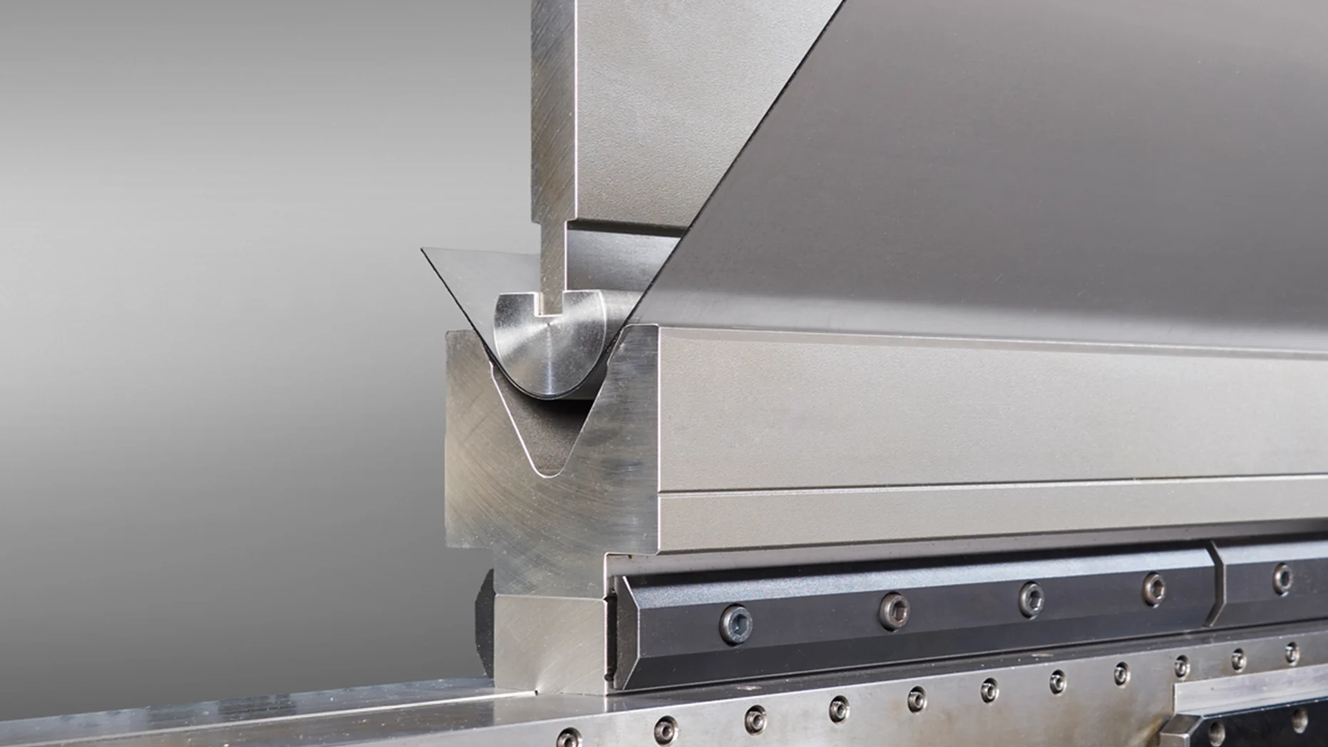
In air bending, the material contacts the punch tip and the two die shoulders. The sheet forms a natural radius across the opening. A wider V generally produces a larger inside radius. A narrower V generally produces a smaller radius, but it also raises force and localized stress.
The punch tip radius still matters. It must be compatible with the material and target geometry, and it must not be used to force an unsafe radius. Air-bending behavior is different from bottoming or coining.
Minimum flange
The flange must remain supported by the die shoulders during the bend. A wider V requires a longer flange. If the flange is too short, it can drop or slide into the opening, causing dimensional error, distortion, or an unstable setup.
Do not use one universal flange coefficient when an exact manufacturer chart is available. Die shoulder radius and the definition of the measured leg can change the published value.
Required force
For the same material, thickness, angle, and bend length, required air-bending force generally decreases as V increases. It also rises approximately with the square of thickness. This is why reducing a V-opening only to achieve a shorter flange can create a large capacity problem.
As a simplified comparison, if force is inversely proportional to V under otherwise identical conditions, moving from 8t to 6t raises force by about 33%, while moving from 8t to 10t lowers it by about 20%. Use this only to understand direction. The final tonnage must come from the approved force chart or calculator.
Bend allowance and flat pattern
Changing V changes the natural inside radius. That can change bend deduction, bend allowance, developed length, and final dimensions. If production uses a different V-opening from the one used to create the flat pattern, verify the bend data before releasing the job.
Step-by-Step V-Die Selection Workflow
A useful chart is the start of the decision, not the end. For the broader tooling sequence, see the guide to choosing press brake tooling.
1. Confirm material and bending method
Record the material specification, grade or tensile strength, thickness and tolerance, bend angle, bend length, target inside radius, minimum flange, grain direction, and surface requirement.
Confirm whether the job is air bending, bottom bending, or coining. The charts in this article are for air bending. Do not apply them directly to another forming method.
2. Choose an initial thickness ratio
Use the manufacturer-based range as a starting point:
– Thin ordinary sheet: often 6–8t
– Common 3–8 mm mild steel: often near 8t
– 9–12 mm mild steel: often near 10t
– Thick plate or high-strength material: often wider, subject to engineering review
3. Match an available die opening
The calculated value may not be a stocked V size. Record both the theoretical value and the actual available die. Use the actual opening for every later radius, flange, force, and bend-allowance check.
4. Check target inside radius
Estimate the natural air-bend radius from the actual V and material. Compare it with the drawing and the material’s minimum permissible radius. If they do not agree, reconsider the V-opening, punch, material orientation, or forming method.
5. Check minimum flange and part clearance
Compare the shortest flange with the exact die chart. Also check nearby features, holes, previous bends, return flanges, backgauge access, and removal clearance.
6. Calculate required force
Use the actual material strength, thickness, V-opening, bend angle, and bend length. Keep units consistent: total tons, tons per foot, kilonewtons per metre, and tonnes per metre are not interchangeable labels.
7. Verify every capacity limit
Check:
– Press brake total available force
– Punch load rating per unit length
– Die load rating per unit length
– Holder, adapter, and clamp ratings
– Short-segment or concentrated-load restrictions
– Working length, crowning, open height, stroke, and daylight
– Tooling interface and safe retention
A machine with enough total tonnage can still overload a short tool segment.
Worked Example 1: 3 mm Mild Steel
Assume:
– Material: ordinary mild steel, exact grade and tensile strength to be confirmed
– Thickness: 3 mm
– Bend method: 90-degree air bending
– Bend length: 1,000 mm
– Target inside radius: about 4 mm
– Minimum flange: 25 mm
Step 1: Calculate an 8t baseline
V = 8 × 3 mm = 24 mm
A stocked V25 die may be the nearest option.
Step 2: Estimate the radius
Using the actual V25 opening:
Inside radius ≈ 0.16 × 25 = 4.0 mm
This matches the target as a preliminary screen.
Step 3: Estimate the minimum flange
Minimum flange ≈ 0.77 × 25 = 19.25 mm
The 25 mm flange is longer than the screening value. Confirm it against the exact V25 die chart and shoulder geometry.
Step 4: Verify force
Do not invent a tonnage value from thickness alone. Enter the confirmed material strength, 3 mm thickness, V25 opening, 1,000 mm length, and bend angle in the approved chart. Check total machine force and the load ratings of the installed punch, die, holder, and clamp.
Step 5: Prove the setup
Run a controlled trial bend under the machine’s approved procedure. Measure angle, radius, flange, and surface condition. Record the actual tooling and correction values.
Worked Example 2: 0.120-Inch Mild Steel
Assume a 0.120-inch mild-steel part with a 90-degree air bend, a 1.0-inch target V-opening, and a 0.90-inch minimum flange.
Step 1: Calculate the baseline
V = 8 × 0.120 = 0.960 in
A 1.000-inch die is a practical candidate.
Step 2: Screen the natural radius
Inside radius ≈ 0.16 × 1.000 = 0.160 in
The drawing must accept that approximate radius, subject to actual material behavior.
Step 3: Screen the flange
Minimum flange ≈ 0.77 × 1.000 = 0.770 in
The 0.90-inch flange passes the preliminary screen. Confirm the exact die’s published minimum.
Step 4: Check force and units
Use an imperial chart that states the material assumption and tons per linear foot, then multiply by the actual bend length in feet. Do not compare tons/ft directly with the press brake’s total tonnage.
Adjusting the Chart for Other Materials
Stainless steel
Stainless steel commonly requires more force and exhibits different springback and natural radius behavior than ordinary mild steel. Do not apply the mild-steel tonnage or radius coefficient without adjustment. Use the actual grade, tensile strength, minimum bend radius, and manufacturer chart.
Aluminum
Aluminum alloys vary widely by alloy and temper. Soft material may need less force, but some heat-treated alloys have limited bendability and can crack if the radius is too tight. Confirm alloy, temper, grain direction, and minimum bend radius.
High-strength steel
High-strength material may require a much wider V-opening and a larger minimum radius. A narrow opening increases force and surface strain quickly. Use the steel producer’s bendability data and the machine/tooling manufacturer’s approved calculation.
Coated and cosmetic sheet
A narrow V can increase contact pressure and marking. Review shoulder radius, cleanliness, protective film, non-marking material, and any resulting effect on repeatability. Validate the setup on representative material.
When a Rolla-V Die May Help
A conventional V-die supports the sheet on fixed shoulders, so a very short flange or mark-sensitive surface can become difficult. A rolling-support or Rolla-V style die may reduce sliding at the contact points and support specific short-flange applications.
Review the CAMT ROLLAR-V die when the drawing cannot be satisfied reliably with a standard fixed V-die. Send the complete part drawing and material details; do not assume a Rolla-V solution removes the need for force, radius, clearance, and compatibility checks.
Common V-Die Selection Problems
| Symptom | Likely mechanism | What to verify | Corrective direction |
|---|---|---|---|
| Inside radius is too large | V-opening is wider than the target permits | Actual V, material, measured radius | Evaluate a narrower safe V or another method; recalculate force |
| Flange falls into the die | Flange is below die support requirement | Actual flange, shoulder geometry, setup position | Smaller safe V, special die, Rolla-V solution, or design change |
| Force is unexpectedly high | V is too narrow, material is stronger/thicker, or units are wrong | Grade/UTS, thickness, V, length, chart units | Stop and recalculate from approved data |
| Part cracks at the bend | Radius/V too tight for material ductility or grain direction | Grade, temper, grain, target radius | Increase radius/V, change orientation or material/process |
| Surface is heavily marked | High contact pressure, contamination, pickup, or sharp shoulders | Die shoulders, cleanliness, coating, protection | Clean, repair, protect, or use application-specific tooling |
| Angle varies along the bend | Deflection, crowning, material variation, wear, or poor seating | Tool seating, alignment, crowning, thickness | Correct the verified mechanism rather than changing V blindly |
| Tool damage or chipping | Load rating or concentrated-load limit exceeded | Tons per length, segment length, holder and die rating | Remove setup from service and obtain engineering approval |
Final Selection Checklist
Before approving a V-die opening, confirm that:
– Material grade, strength, thickness, and tolerance are documented.
– Air bending is the intended method.
– The theoretical V has been matched to an actual available die.
– The predicted inside radius agrees with the drawing and material limits.
– The shortest flange is supported by the exact die geometry.
– Force is calculated for the actual material, angle, opening, and bend length.
– Machine, punch, die, holder, clamp, adapter, and short-segment ratings are satisfied.
– The selected V is reflected in bend allowance and flat-pattern data.
– Part collision, backgauge access, stroke, open height, and removal clearance are checked.
– A controlled trial bend and inspection plan are defined.
A press brake V die opening chart is most useful when it narrows the choices without hiding the engineering checks. Start with the appropriate thickness ratio, use the actual die opening, and verify radius, flange, force, capacity, and the finished part.
For a CAMT tooling review, send Harmon Tech the part drawing, material and grade, thickness, bend angle and radius, minimum flange, bend length, press brake model, clamping system, and required segmentation.
11. FAQ
1. What is the Rule of 8 for press brake V-dies?
For ordinary mild-steel air bending, the Rule of 8 uses a V-opening approximately eight times material thickness. It is a starting point, not a universal rule. Thin sheet, thick plate, high-strength material, short flanges, and specific radius requirements may need a different ratio.
2. What V-die opening should I use for 3 mm mild steel?
An 8t baseline gives 24 mm, so V24 or the nearest suitable standard size such as V25 may be considered. Then verify the expected inside radius, minimum flange, required force, exact die load rating, and press brake capacity.
3. How does V-die opening affect inside bend radius?
In air bending, a wider V generally produces a larger natural inside radius, while a narrower V produces a smaller radius and higher force. The relationship changes with material, angle, tooling geometry, and forming method.
4. How do I calculate minimum flange length from V-opening?
For preliminary mild-steel air-bending screening, some guidance uses approximately 0.70–0.77 times V. The exact value depends on die shoulder geometry and measurement convention, so use the minimum-flange value in the chart for the actual die.
5. Can I use the same V-die chart for stainless steel?
Not without adjustment. Stainless steel can require more force and may produce different springback and radius behavior. Use the actual grade and tensile strength, material bendability data, and an approved tooling force chart.
6. Why does a narrower V-opening increase press brake tonnage?
A narrower opening reduces the span over which the sheet is bent, so the press must apply more force to form the same thickness and length. It also raises localized stress on the material and tooling.
7. Can an air-bending V-die chart be used for bottom bending or coining?
No. Bottom bending and coining use different tool contact and much higher force conditions. Use the machine and tooling manufacturer’s method-specific chart and instructions.