How Do You Calculate Press Brake Tonnage for Air Bending?
A press brake tonnage chart estimates the force needed to air-bend a given material thickness over a selected V-die opening. Read the chart value as force per unit length, multiply it by the actual bend length, adjust only with documented material and tooling factors, and compare the result with both machine capacity and every tooling load rating.
The calculation is a planning estimate. Material strength, thickness tolerance, grain direction, friction, tool condition and the actual forming method can change the load.
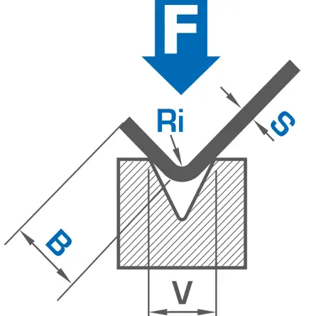
What Does Press Brake Tonnage Mean?
Press brake tonnage is the forming force applied along the bend. A machine may be described by its total nominal capacity, such as 100 US tons or 100 metric tonnes-force, while a bending force chart normally reports a load per foot or per meter. Those numbers are not interchangeable.
| Value | Typical unit | What it describes | Common mistake |
|---|---|---|---|
| Force per unit length | US tons/ft, metric tf/m or kN/m | Chart value for a continuous bend | Comparing it directly with total machine tonnage |
| Total calculated force | US tons, metric tf or kN | Estimated force for the actual bend length | Ignoring material, method or special-tool factors |
| Machine nominal capacity | US tons, metric tf or kN | Maximum stated press capacity under defined conditions | Assuming full capacity is available at every position and length |
| Tool load rating | tons/ft, tf/m or kN/m | Allowable load for a punch, die, holder or adapter | Checking the machine but not the tooling |
What Is the Air-Bending Tonnage Formula?
Bystronic’s press brake tonnage calculation gives the following imperial formula for conventional air bending. It uses 60,000 psi AISI 1035 as its baseline and adds separate factors for material, forming method and multiple-bend tooling.
| Symbol | Meaning | Unit or baseline |
|---|---|---|
| T | Total calculated forming force | US short tons |
| t | Material thickness | inches |
| V | V-die opening width | inches |
| L | Actual bend length | inches |
| M | Material factor | Actual tensile strength in psi ÷ 60,000 psi |
| B | Bending-method factor | 1.0 for the formula’s air-bending baseline |
| G | Multiple-bend or special-tooling factor | 1.0 for conventional single-bend tooling |
Before inserting a factor for bottoming, coining, hemming, offset or multi-bend tooling, use the tool and press manufacturer’s documented method. A general air-bending formula is not a safe substitute for an application-specific load chart.
How Do You Convert the Formula to Tonnage per Meter?
For the same 60,000 psi mild-steel baseline, the Bystronic imperial constant converts approximately to these screening relationships:
Kilonewtons per meter ≈ 661 × t² ÷ V
Here, t and V are both in millimeters. Multiply the per-meter result by bend length in meters to estimate total load. These are unit conversions of one manufacturer’s empirical baseline, not universal standards.
Press Brake Tonnage Chart for 90-Degree Air Bending
These tables are formula-derived screening values for 60,000 psi mild steel, conventional tooling and a V-opening near eight times thickness. They help estimate scale and check arithmetic. Do not use them in place of the machine and tooling manufacturers’ current charts.
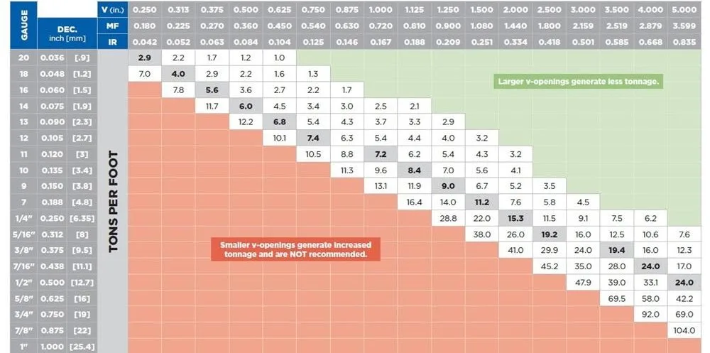
Metric bending force chart
| Thickness t (mm) | Example V-opening (mm) | Approx. tf/m | Approx. kN/m |
|---|---|---|---|
| 1.0 | 8 | 8.4 | 83 |
| 1.5 | 12 | 12.6 | 124 |
| 2.0 | 16 | 16.9 | 165 |
| 3.0 | 24 | 25.3 | 248 |
| 4.0 | 32 | 33.7 | 331 |
| 5.0 | 40 | 42.1 | 413 |
| 6.0 | 48 | 50.6 | 496 |
| 8.0 | 64 | 67.4 | 661 |
Imperial bending force chart
| Thickness t (in) | Example V-opening (in) | Approx. US tons/ft |
|---|---|---|
| 0.060 | 0.500 | 4.1 |
| 0.075 | 0.625 | 5.2 |
| 0.105 | 0.875 | 7.2 |
| 0.125 | 1.000 | 9.0 |
| 0.1875 | 1.500 | 13.5 |
| 0.250 | 2.000 | 18.0 |
| 0.375 | 3.000 | 27.0 |
| 0.500 | 4.000 | 35.9 |
WILA’s air-bending tonnage chart is a useful manufacturer cross-check because it publishes both metric and imperial tables and states the material and method assumptions. Reputable charts can differ because their material baseline, coefficients, die geometry and rounding conventions differ.
How Do You Calculate Total Tonnage Step by Step?
- Confirm the method. This article covers conventional air bending, not bottoming, coining, hemming or multi-bend forming.
- Identify material strength. Use the certified maximum tensile strength or the factor required by the selected chart.
- Measure thickness. Because thickness is squared, small input errors can materially change the result.
- Select a workable V-opening. Check radius, minimum flange and ductility before calculating force.
- Read or calculate force per unit length. Keep US tons, metric tonnes-force and kN separate.
- Multiply by bend length. Convert inches to feet or millimeters to meters before using a per-length value.
- Apply only documented factors. Do not guess material, method or tooling multipliers.
- Verify every capacity. Check the press, punch, die, holder, adapter, clamp and short segments.
Illustrative example: 1/8-inch mild steel over a 1-inch V-die
Assume conventional 90-degree air bending of 60,000 psi mild steel with a 72-inch bend length, 0.125-inch thickness and 1.000-inch V-opening. Use material, method and conventional-tool factors of 1.0.
Bend length = 72 in ÷ 12 = 6 ft
Total calculated force = 8.984 × 6 = 53.91 US tons
The arithmetic result is about 53.9 US tons. It does not automatically authorize a 55-ton machine or tool. Verify usable machine capacity for the bend location and length, continuous and concentrated tool ratings, material data and any reserve required by the manufacturer.
How Does the V-Die Opening Change Required Force?
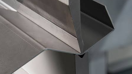
For the stated formula, force is inversely proportional to V-opening. If every other input remains unchanged, reducing a 1-inch opening to 0.75 inch increases calculated force by one third. Increasing it to 1.25 inches reduces calculated force by 20%.
A wider die is not automatically better. It normally increases the natural inside radius and the minimum supported flange. A narrower die may help a radius or flange requirement, but it raises load, contact pressure, marking risk and wear. Use CAMT’s press brake V-die opening chart to screen geometry before finalizing the force calculation.
Which Variables Change a Press Brake Tonnage Calculation?
| Variable | Relationship | Practical consequence |
|---|---|---|
| Thickness | Force scales approximately with t² | A 10% thickness increase produces about a 21% calculated force increase before other changes |
| Bend length | Force changes linearly | Doubling continuous bend length doubles total calculated force |
| V-opening | Force changes inversely | A narrower opening raises load while changing radius and flange support |
| Tensile strength | The factor follows strength relative to the chart baseline | Grade and condition matter more than a generic metal-family name |
| Forming method | Air bending, bottoming and coining require different treatment | An air-bend chart can seriously understate a non-air-bending load |
| Tool geometry | Offset, hat, hemming and multiple-bend tools redistribute load | Use application-specific load analysis |
| Condition | Friction, work hardening, coating, wear and alignment affect actual force | Calculated and measured loads may differ |
How Should You Use a Press Brake Force Calculator?
A press brake force calculator is most useful as an auditable version of a chart. Record every input and the source of each factor. If the result cannot show its units, material baseline, bend method and die-opening definition, it should not control a production decision.
The Cincinnati press brake tonnage calculator explicitly limits its estimate to air bends and states a V-die range of five to nineteen times material thickness. That boundary matters: a calculator is not automatically valid outside its documented range.
Why Must Machine and Tooling Capacity Be Checked Separately?
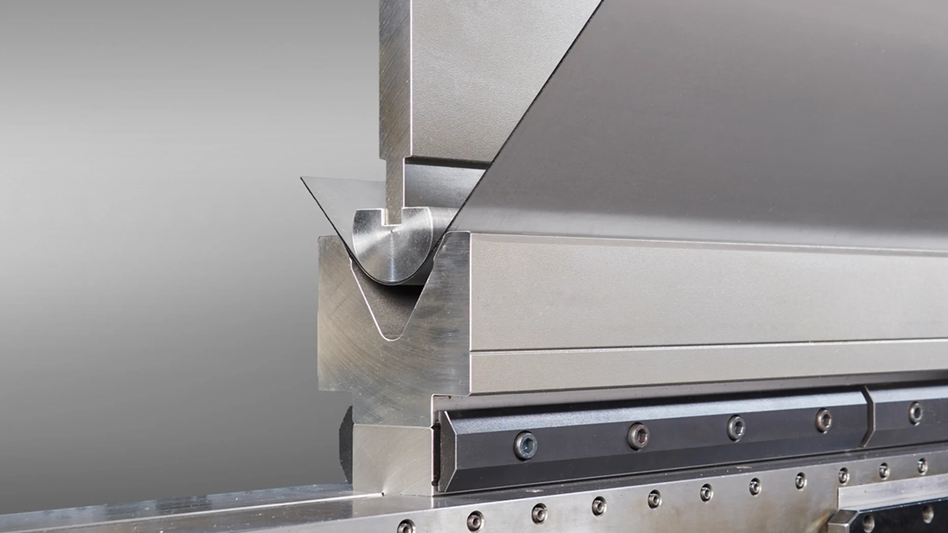
A 200-ton press brake can still overload a punch, V-die, holder or adapter rated below the required force per unit length. The reverse is also true: high-capacity tooling does not increase the machine’s rated capacity.
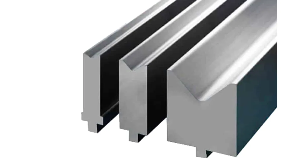
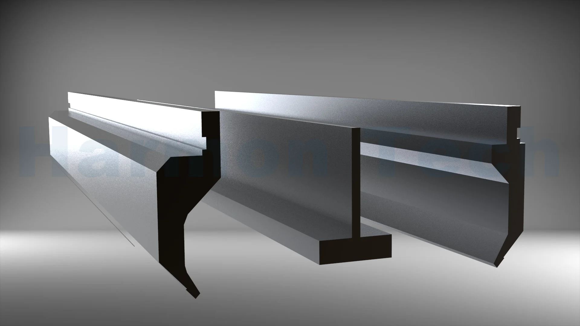
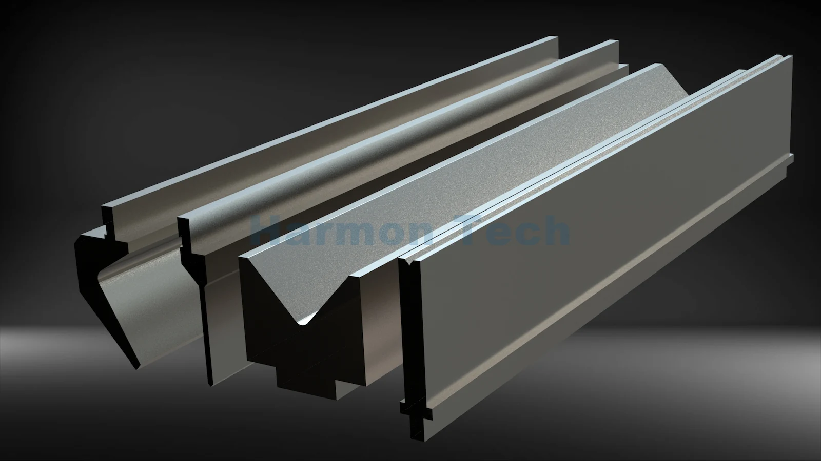
After calculating total force, review how to choose press brake tooling and verify the complete load path. Check the punch, die, holder, clamp, adapter, crowning system, bed and ram restrictions in the same units and for the actual installed segment lengths.
What Is Concentrated Loading?
Concentrated loading occurs when a high total force is applied through a short bend or tooling segment. Overall machine tonnage may appear adequate while local load per foot or meter exceeds the punch, die, holder or machine’s permitted short-length load.
| Load case | Main risk | Required check |
|---|---|---|
| Long centered bend | Total press capacity and distributed tool load | Verify force over the full loaded length |
| Short centered bend | High local force per unit length | Verify minimum loaded length and concentrated-load rating |
| Short off-center bend | Local tool overload plus machine imbalance | Verify the approved loading zone and off-center limit |
| Segmented tooling | Too little installed support length | Verify every segment, joint, holder and adapter rating |
Do not divide total machine tonnage by bed length and assume the answer is safe everywhere. Manufacturers may publish minimum bending lengths, central loading zones, off-center limits or reduced ratings for short segments. Segmented tooling needs enough installed length and correct positioning to distribute load safely.
What Are the Most Common Tonnage-Calculation Errors?
| Error | Why it fails | Correction |
|---|---|---|
| Mixing tons/ft with total tons | The chart value has not been multiplied by length | Convert length to the chart unit, then calculate total force |
| Mixing US tons and metric tf | The numerical values differ by about 9.3% | Label and convert units before comparison |
| Using nominal material type only | Strength varies by grade and condition | Use certificates or an approved grade-specific factor |
| Using an air-bend formula for bottoming | Contact and forming depth are different | Use method-specific manufacturer data |
| Changing V only to reduce force | Radius and minimum flange also change | Recheck geometry and force together |
| Checking only the machine | Tooling or adapters can have a lower rating | Verify every component in the load path |
| Ignoring short-bend limits | Local load can exceed a concentrated-load limit | Check minimum loaded length and position |
Frequently Asked Questions
How is press brake tonnage calculated?
For conventional 90-degree air bending, use an approved formula or chart with material strength, thickness, V-opening and bend length. Calculate force per foot or meter, convert it to total force, apply only documented factors, and check both machine and tooling capacities.
Is press brake tonnage calculated per meter or for the whole bend?
Charts commonly show force per meter or foot. Multiply that value by the actual bend length in the same unit to obtain total calculated force. Machine tonnage is normally a total rating, while tooling may be rated per unit length.
Why does thickness have such a large effect on force?
Thickness is squared in the cited air-bending relationship. With other inputs unchanged, doubling thickness produces roughly four times the calculated force. The suitable V-opening may also change, so recalculate the complete setup.
Does a wider V-die reduce press brake tonnage?
Yes, a wider opening reduces calculated air-bending force when other inputs remain unchanged. It also produces a larger natural radius and requires a longer supported flange, so it must satisfy the drawing as well as the load requirement.
Can I use a mild-steel chart for stainless steel?
Not without a documented correction. Use the actual grade’s tensile strength or the factor published by the chart or machine manufacturer. A generic stainless multiplier may not represent every alloy, temper or batch.
How much extra press capacity should I allow?
Use the reserve or sizing guidance published by the selected machine and tooling manufacturer. Do not add a universal margin and assume the setup is safe; capacity can depend on position, loaded length, tooling and operating mode.
Can a short bend overload press brake tooling?
Yes. A short bend can concentrate force into a small tool length even when total tonnage is below the machine rating. Check each component’s concentrated-load limit, minimum loaded length, segment arrangement and approved load position.
How Should You Apply a Press Brake Tonnage Chart?
Use a press brake tonnage chart to establish a transparent preliminary load, not to bypass manufacturer data. Confirm the material and method, select a V-opening that meets radius and flange requirements, calculate total force in consistent units, and verify the entire machine-to-tool load path.
Request a CAMT tooling review.
Send Harmon Tech the part drawing, material grade and tensile-strength data, thickness, bend angle and inside radius, bend length, candidate V-opening, press brake model and capacity, clamping system, tooling drawings and required segmentation. CAMT can review the tooling configuration and load questions before quotation.