How Do You Use a Press Brake Bend Radius Chart?
A Press Brake Bend Radius Chart helps you estimate the inside radius that an air-bending setup will naturally form. For ordinary mild steel bent to about 90 degrees, a practical starting estimate is an inside radius equal to roughly 15–16% of the V-die opening. The result must then be checked against the actual material, flange length, punch, force and manufacturer’s tooling chart.
What Does a Press Brake Bend Radius Chart Actually Show?
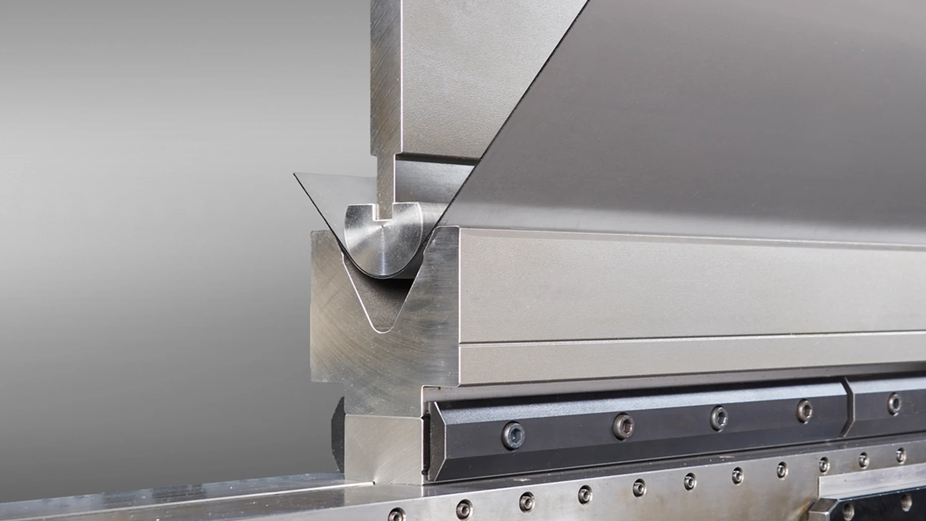
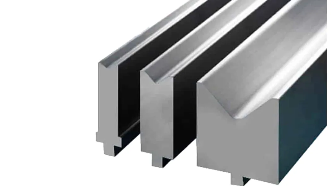
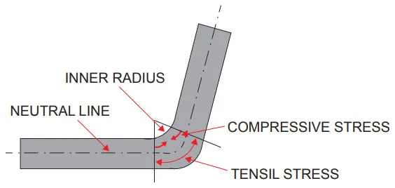
The useful output is the inside bend radius: the radius measured on the inside surface of the formed part. In air bending, the sheet contacts the punch nose and the two die shoulders while the material remains above the bottom of the V. The inside radius develops naturally from the opening, the material response and the bend angle.
This is why a bend-radius chart is not simply a list of punch-tip radii. WILA’s guidance on V-opening size explains that the air-bent product radius is not equal to the tool-tip radius and that changing the V-opening also changes force, marking, minimum leg length and the flat pattern.
| Term | What it means | What mainly controls it | Why it matters |
|---|---|---|---|
| Specified inside radius | The radius required on the drawing | Part design and functional requirement | It is the target that tooling and process must reproduce. |
| Natural air-bend radius | The radius the material forms while floating over the V-die | V-opening, material properties and bend angle | This is the radius estimated by the main chart in this article. |
| Punch-tip radius | The physical nose radius of the upper tool | Punch geometry | It affects pressure and compatibility but does not automatically equal the air-bent radius. |
| Minimum material radius | The smallest radius the material can accept without unacceptable cracking or damage | Grade, temper, tensile strength, ductility, thickness and grain direction | It is a material/formability limit, not a universal press-brake setting. |
What Is the Air-Bending Radius Formula?
For ordinary mild steel in approximately 90-degree air bending, use the following starting relationship:
Ri is the estimated inside radius and V is the actual die opening, both in the same unit. Bystronic’s rules of press brake tool selection use approximately 16% of the V-opening for air-bending mild steel. The same source presents V ≈ 8 × thickness as a common starting point and warns that a V-opening below five times thickness can reduce accuracy, damage tooling or the machine and create an unsafe condition.
Combining the two preliminary relationships gives:
This explains why many conventional mild-steel air bends produce an inside radius around one material thickness. It does not prove that every material should be designed with Ri = t. Material strength, angle, thickness range and the available die can move the actual result.
Press Brake Bend Radius Chart in Millimetres
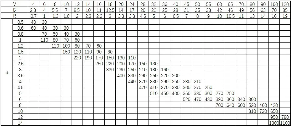
The following table is calculated from Ri = 0.16V and minimum flange ≈ 0.77V. It is intended for preliminary selection of ordinary mild-steel air bends near 90 degrees. The flange figure is a screening estimate; use the exact tooling manufacturer’s definition and chart for production.
| V-die opening V (mm) | Estimated inside radius Ri (mm) | Estimated minimum flange (mm) | 8t thickness reference (mm) |
|---|---|---|---|
| 4 | 0.6 | 3.1 | 0.5 |
| 6 | 1.0 | 4.6 | 0.75 |
| 8 | 1.3 | 6.2 | 1.0 |
| 10 | 1.6 | 7.7 | 1.25 |
| 12 | 1.9 | 9.2 | 1.5 |
| 16 | 2.6 | 12.3 | 2.0 |
| 20 | 3.2 | 15.4 | 2.5 |
| 24 | 3.8 | 18.5 | 3.0 |
| 30 | 4.8 | 23.1 | 3.75 |
| 40 | 6.4 | 30.8 | 5.0 |
| 50 | 8.0 | 38.5 | 6.25 |
| 60 | 9.6 | 46.2 | 7.5 |
| 80 | 12.8 | 61.6 | 10.0 |
| 100 | 16.0 | 77.0 | 12.5 |
Always use the opening actually measured or specified for the installed die. Nominal tool sizes may be rounded, and manufacturers can define the V-opening at different geometric points.
Press Brake Bend Radius Chart in Inches
| V-die opening V (in) | Estimated inside radius Ri (in) | Estimated minimum flange (in) | 8t thickness reference (in) |
|---|---|---|---|
| 0.250 | 0.040 | 0.193 | 0.031 |
| 0.375 | 0.060 | 0.289 | 0.047 |
| 0.500 | 0.080 | 0.385 | 0.063 |
| 0.625 | 0.100 | 0.481 | 0.078 |
| 0.750 | 0.120 | 0.578 | 0.094 |
| 0.875 | 0.140 | 0.674 | 0.109 |
| 1.000 | 0.160 | 0.770 | 0.125 |
| 1.250 | 0.200 | 0.963 | 0.156 |
| 1.500 | 0.240 | 1.155 | 0.188 |
| 2.000 | 0.320 | 1.540 | 0.250 |
| 2.500 | 0.400 | 1.925 | 0.313 |
| 3.000 | 0.480 | 2.310 | 0.375 |
| 4.000 | 0.640 | 3.080 | 0.500 |
| 5.000 | 0.800 | 3.850 | 0.625 |
How Do You Work Backward From a Required Inside Radius?
If the drawing gives the inside radius, rearrange the mild-steel air-bending estimate:
Illustrative example: 2 mm mild steel with a 3 mm target radius
- State the assumptions: ordinary mild steel, 2.0 mm nominal thickness, about 90 degrees, air bending, 1,000 mm bend length and an 18 mm minimum flange.
- Calculate the theoretical opening: V ≈ 3 ÷ 0.16 = 18.75 mm.
- Choose an available opening: a 20 mm V-die is a practical candidate.
- Recalculate the radius: Ri ≈ 0.16 × 20 = 3.2 mm.
- Check the V/thickness ratio: 20 ÷ 2 = 10. This is wider than the common 8t starting point, so expect a larger radius and lower force than a narrower die, while checking the part’s flat pattern.
- Screen the flange: 0.77 × 20 = 15.4 mm. The 18 mm flange clears this preliminary estimate, but the exact die chart still governs.
- Complete the capacity check: obtain force per unit length from the machine or tooling manufacturer’s chart for the actual material strength, multiply by the 1 m bend length and compare it with the press, tool, holder and concentrated-load ratings.
- Prove the setup: make a controlled trial bend, measure the inside radius and angle, then update the bend deduction or control data from the actual result.
This example narrows the tooling choice; it does not authorize a machine setup. If the drawing tolerance on radius is tight, validate the specific material batch rather than treating 3.2 mm as a guaranteed result.
How Do Material and Bend Angle Change the Radius?
The 16% relationship is a mild-steel air-bending rule, not a material-independent law. A material with different tensile strength, ductility or temper can form a different natural radius over the same V-opening. Rolling direction and batch variation can also change springback and cracking risk.
Before applying the chart to stainless steel, aluminum or high-strength steel, obtain the material grade and tensile-strength range, consult the material supplier’s minimum-radius guidance and use the tooling manufacturer’s material-specific chart or simulation. Do not apply an invented universal multiplier.
| Variable | Typical effect | Verification |
|---|---|---|
| Higher tensile strength | Can increase the naturally formed radius and springback for the same opening | Use the actual grade/strength and a material-specific manufacturer chart. |
| Rolling direction | Can change formability and the risk of cracking at a tight radius | Confirm grain orientation and material-supplier guidance. |
| Thickness tolerance | Changes force, springback and how the sheet interacts with the tooling | Measure representative sheets and trial-bend the production batch. |
| Bend angle | Changes the contact and natural-radius relationship | Use a chart or simulation for the intended final angle. |
| V-opening measurement convention | Two nominally similar dies may not represent the same working opening | Use the manufacturer’s dimensioned tool drawing. |
| Tool wear or damage | Can change contact points, marking and repeatability | Inspect the punch nose and die shoulders before setup. |
Does the Punch-Tip Radius Equal the Inside Radius?
Usually not in conventional air bending. The V-opening and the material’s behavior establish the natural radius. The punch nose must still be suitable: a very sharp nose concentrates pressure, while an oversized radius can interfere with the intended air-bending geometry.
Bottom bending and coining are different. The sheet is driven into more complete contact with the tooling, so the punch radius has a stronger influence and the required force rises. Use method-specific manufacturer data; never use an air-bend radius table to approve a bottoming or coining setup.
For a broader selection sequence that includes V-opening, punch profile, load and compatibility, see CAMT’s guide on how to choose press brake tooling.
When Do You Need a Radius Punch or Special Radius Tool?
A standard air-bending setup is efficient when the target radius is close to the natural radius generated by an available V-opening. A larger controlled radius, a demanding profile tolerance or a radius that cannot be achieved without an impractically wide die may require a radius punch, replaceable radius bar, multi-radius tool or staged forming process.
WILA’s large-radius bending guidance warns about multi-breakage, where the sheet separates from an oversized punch and forms a non-circular profile. Its application-specific relationships and force corrections should be used only under WILA’s stated conditions and checked against the selected tooling system.
Review CAMT radius tooling options when the part requires a deliberately controlled large radius. Provide the part drawing, material grade and strength, thickness, bend length, target radius and tolerance, press-brake model, clamping interface, available stroke/open height, surface requirement and expected quantity.
How Does Inside Radius Affect Bend Allowance?
The inside radius is also an input to flat-pattern development. One common geometric form is:
The K-factor represents the assumed neutral-axis location through the thickness. It should be calibrated from the actual material, tooling and bending process rather than copied blindly from a generic table.
For an illustrative 90-degree bend with t = 2.0 mm, Ri = 3.0 mm and K = 0.38:
If the actual radius is 2.4 mm instead, the same assumed K-factor gives about 4.96 mm. That difference is large enough to change finished flange dimensions, which is why changing the V-die without updating the flat pattern can create a repeatable dimensional error.
What Should You Check Before Releasing the Setup?
| Step | Decision | Required evidence |
|---|---|---|
| 1 | Define the target | Drawing radius, tolerance, angle, flange and surface requirement |
| 2 | Identify the material | Grade, tensile-strength range, thickness/tolerance, temper and grain direction |
| 3 | Select the method | Air bending, bottoming, coining or radius forming |
| 4 | Estimate the V-opening | Manufacturer rule/chart and actual available die openings |
| 5 | Check geometry | Predicted radius, minimum flange, punch nose, die shoulders and part clearance |
| 6 | Check load | Force per unit length, bend length, press/tool/holder ratings and concentrated-load limits |
| 7 | Check compatibility | Tooling interface, holder drawing, working height, stroke, daylight and segmentation |
| 8 | Validate | Controlled trial bend, radius/angle measurement and corrected bend data |
Why Does the Measured Radius Miss the Chart?
| Symptom | Possible mechanism | What to check | Corrective direction |
|---|---|---|---|
| Radius is larger than expected | Opening is wider than assumed, material is stronger, or the chart conditions do not match | Measure the actual V, confirm grade/strength and verify bend method | Use the correct material-specific chart or an approved smaller opening after load and flange checks. |
| Radius is smaller than expected | Opening is narrower, the operation is approaching bottoming, or the assumed formula is wrong | Inspect ram depth, tool angles, contact pattern and V dimension | Restore the intended air gap or revise the documented setup. |
| Cracks at the outside of the bend | Radius is too tight for the material/rolling direction or the punch pressure is too concentrated | Confirm grade, temper, grain, edge quality and punch nose | Increase the radius/V-opening or change orientation/process with material-supplier guidance. |
| Large radius is not circular | Multi-breakage or separation between the sheet and radius punch | Compare punch radius, V-opening, thickness and contact sequence | Use validated large-radius tooling geometry or staged forming. |
| Radius varies along the bend | Material variation, uneven loading, misalignment, worn tooling or crowning error | Measure thickness/strength, alignment, tool condition, force distribution and crowning | Correct the verified source; do not compensate blindly with more penetration. |
Frequently Asked Questions
What determines the inside radius in press brake air bending?
The V-die opening, material properties and bend angle are the main influences. For ordinary mild steel near 90 degrees, Ri ≈ 0.15–0.16V is a useful starting range, but the selected manufacturer’s chart and a trial bend should confirm it.
Is the inside bend radius the same as the punch-tip radius?
Not usually in air bending. The material floats over the V-die and forms a natural radius. The punch-tip radius still affects pressure and suitability, while bottom bending, coining and dedicated radius forming give the upper tool a stronger role.
What is the formula for press brake bend radius?
For preliminary mild-steel air bending near 90 degrees, use Ri ≈ 0.16V. Work backward with V ≈ Ri/0.16. Do not use that relationship as a universal formula for stainless, aluminum, high-strength steel, bottoming or coining.
Can I use the same bend-radius chart for stainless steel and aluminum?
No. Different grades and tempers can form different radii and springback over the same opening. Use the material’s actual grade and strength with a manufacturer’s material-specific chart or simulation, then validate the production batch.
How can I make a smaller inside radius?
A smaller V-opening can reduce the natural radius, but it also increases force, local stress, marking and tool wear. Never narrow the die solely to chase a radius; check material formability, flange support, press capacity and every tooling load rating.
When should I use a radius punch?
Use a radius punch or special radius tool when the target is substantially larger or more controlled than the natural radius available from standard air-bending tooling. The punch, V-opening, material thickness and springback must be engineered together to prevent a non-circular bend.
How accurate is a press brake bend radius chart?
It is accurate enough to shortlist tooling only when its material, angle, method and measurement convention match the job. Tight tolerances require a documented trial bend, radius measurement and calibrated bend allowance or bend deduction.
Conclusion: How Should You Apply the Chart?
Use a Press Brake Bend Radius Chart to choose a starting V-opening, not to bypass engineering checks. For ordinary mild-steel air bending near 90 degrees, Ri ≈ 0.16V is a practical first estimate. Then confirm the actual material, minimum flange, punch geometry, method, force, tool and machine capacity, flat pattern and measured trial result.
Need a Radius-Tooling Review?
Send Harmon Tech the part drawing, material grade and thickness, target inside radius and tolerance, bend length, press-brake model, clamping interface and available tooling. CAMT can review whether a standard air-bending setup or application-specific radius tool is the better starting point.