How Do You Calculate the Inside Bend Radius on a Press Brake?
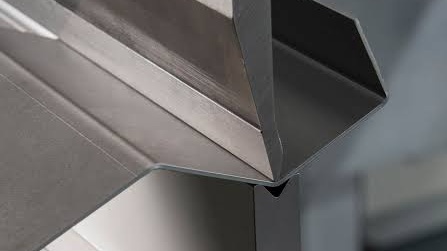
To estimate press brake bend radius in conventional air bending, start with the actual V-die opening and the material. For ordinary mild steel bent to approximately 90 degrees, a practical screening relationship is inside radius Ri ≈ 0.16 × V. The result is a starting estimate, not a universal material limit or production approval.
After calculating the radius, verify material grade, thickness, rolling direction, minimum flange, punch tip, forming force, tool capacity and the measured result from a controlled trial bend.
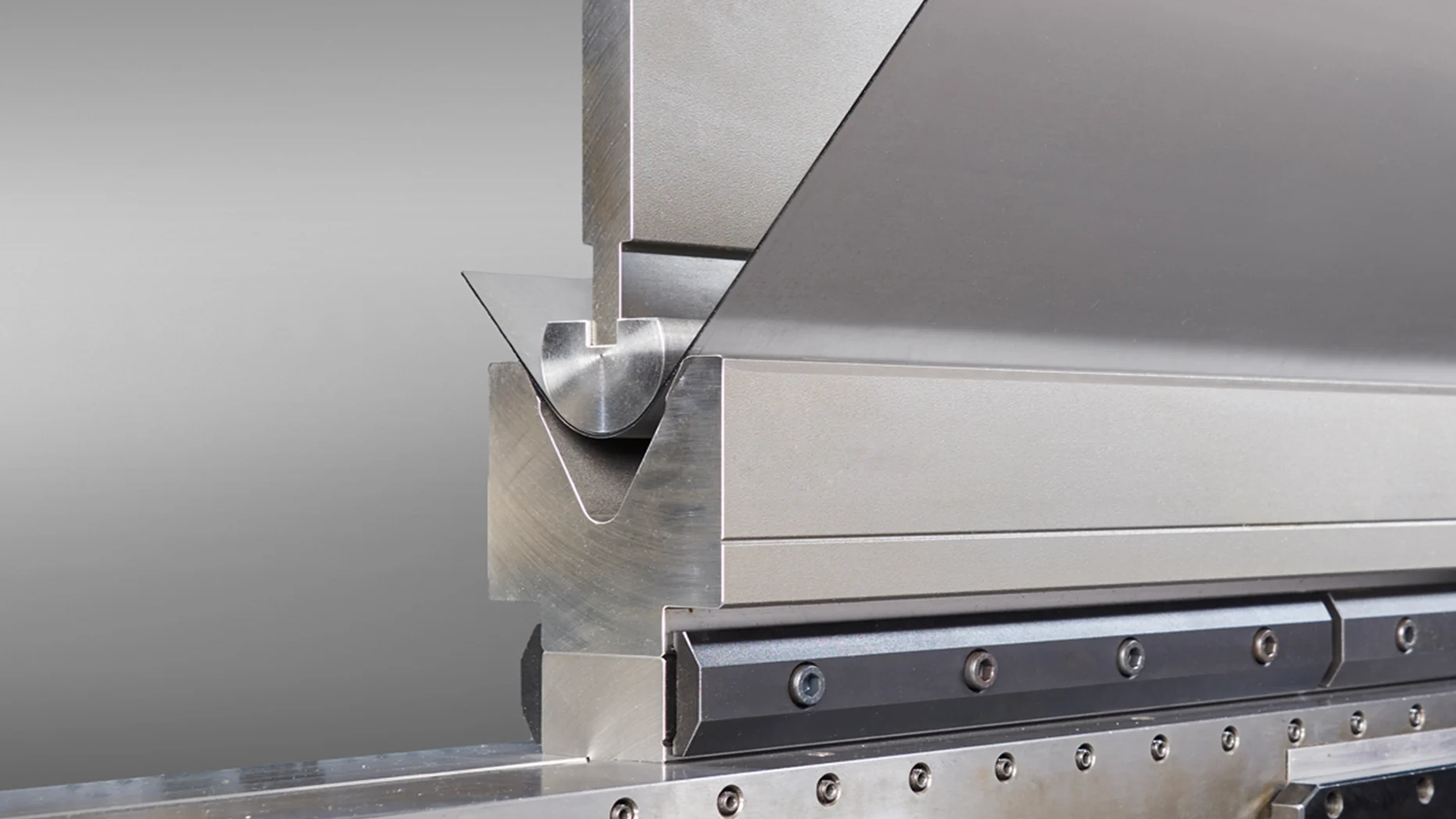
Which Bend Radius Are You Calculating?
Most sheet-metal drawings specify the inside bend radius, measured on the inside surface of the finished bend. That value must not be confused with the punch-tip radius or the minimum radius a material can tolerate without unacceptable cracking.
| Radius term | Meaning | Main control | Why it matters |
|---|---|---|---|
| Specified inside radius | Radius required by the drawing | Product design | The process and tooling must reproduce it within the stated tolerance |
| Natural air-bend radius | Radius formed while the sheet floats over the V | V opening, material and bend angle | This is the radius estimated by Ri ≈ 0.16V for the stated baseline |
| Punch-tip radius | Physical nose radius of the upper tool | Punch geometry | It affects contact pressure and suitability but does not automatically equal Ri |
| Minimum material radius | Smallest acceptable radius under defined conditions | Grade, temper, thickness, ductility and grain direction | It is a formability limit, not a universal press-brake setting |
| Outside radius | Radius on the outside surface | Ri plus material thickness approximately | Used for envelope and clearance checks |
Does the Bending Method Change the Radius?
Yes. The air-bending relationship applies only when the sheet contacts the punch and the two die shoulders without being forced fully into the die. Bottom bending, coining and dedicated radius forming create different contact conditions.
| Method | How the radius is controlled | Tool relationship | Calculation implication |
|---|---|---|---|
| Air bending | Natural radius forms over the V opening | V opening and material dominate; punch must remain compatible | Use a material- and angle-specific chart or preliminary V-based relationship |
| Bottom bending | Material approaches fuller contact with the die | Punch and die geometry have stronger influence | Do not apply an air-bending coefficient without method-specific data |
| Coining | High pressure forces material into the tooling | Tool geometry strongly defines the bend | Requires different load and radius rules |
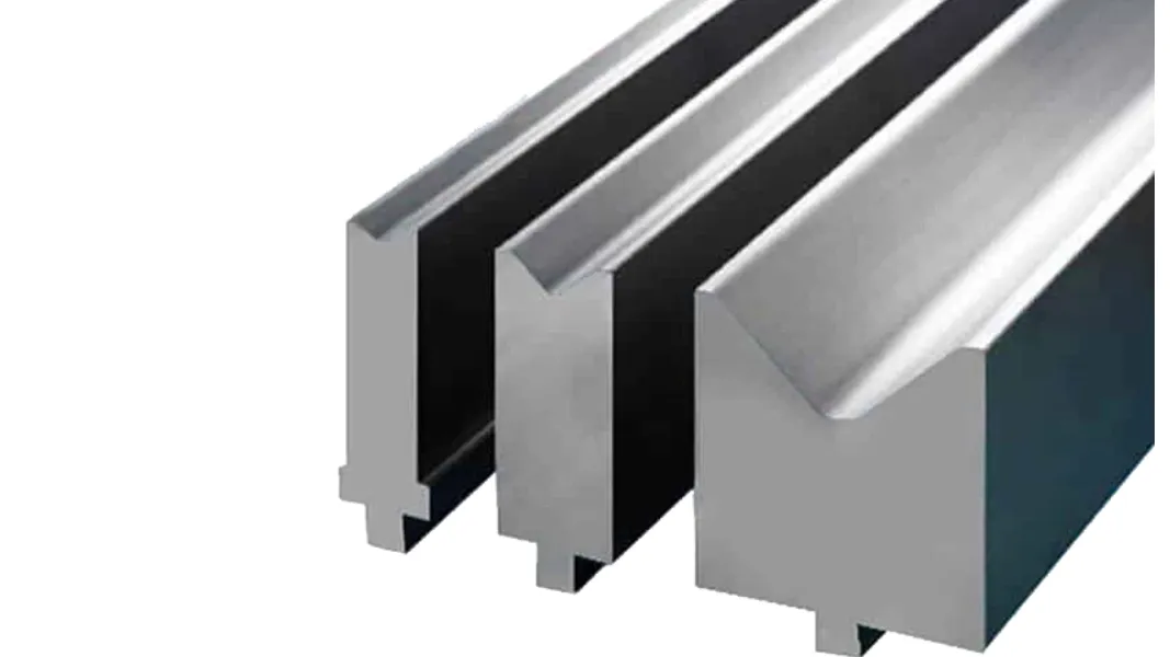
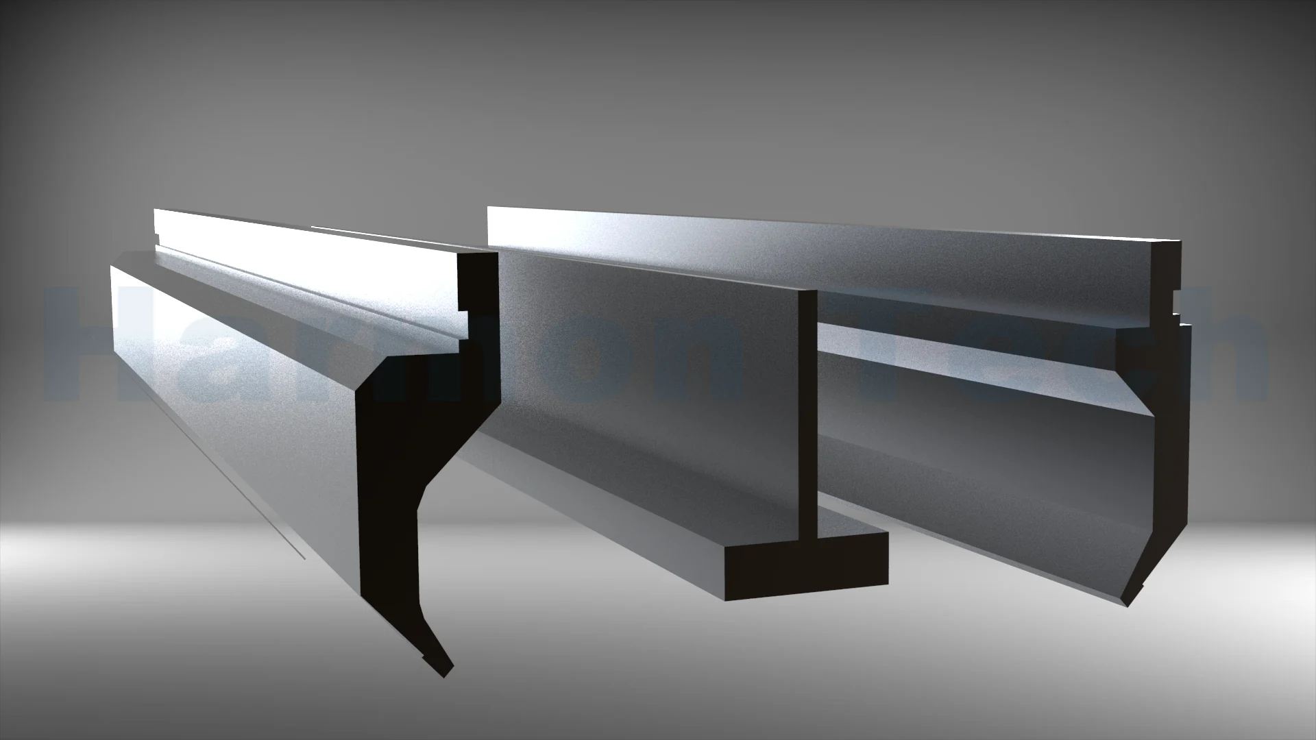
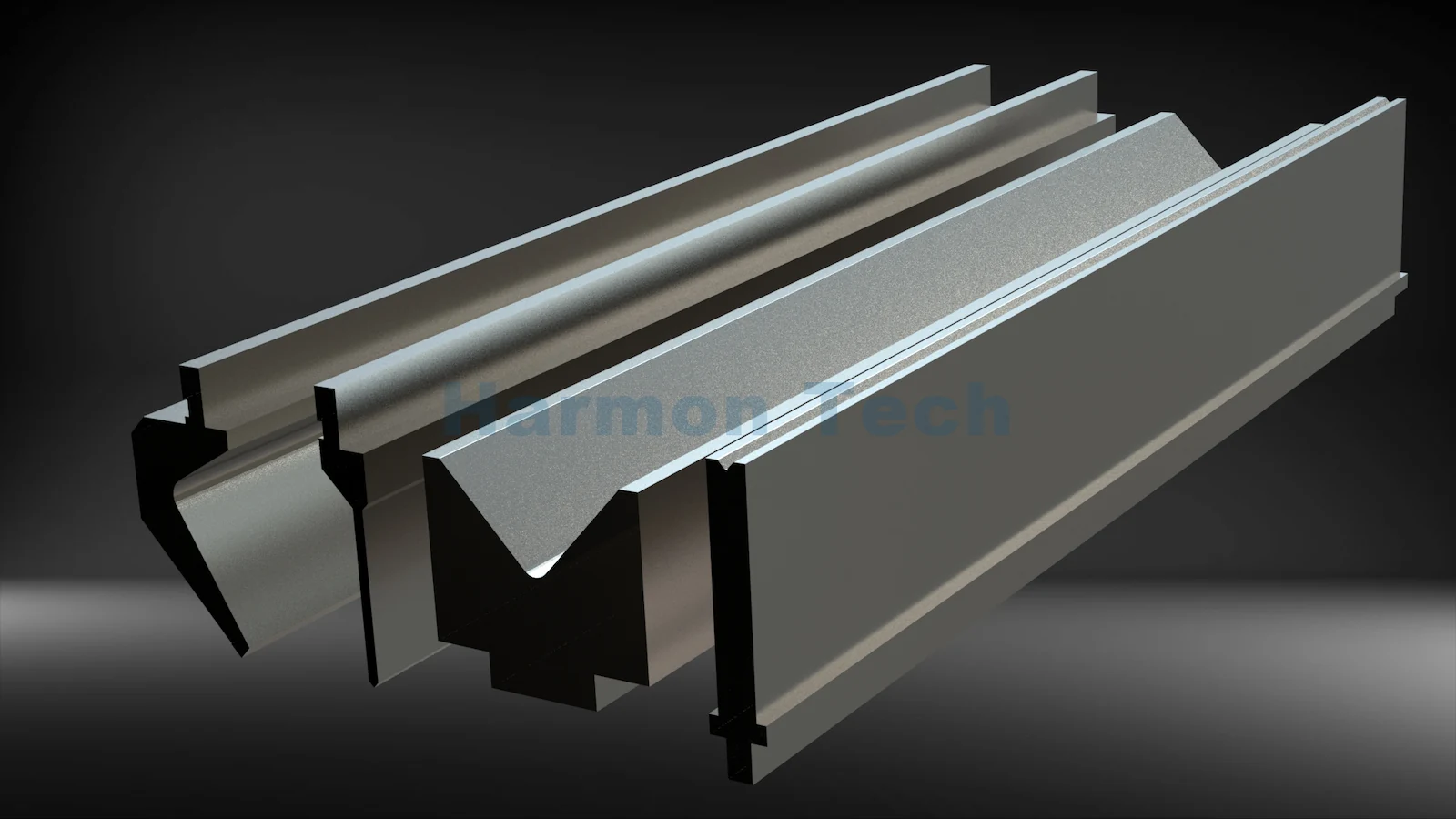
| Radius tooling | A large punch radius or designed tool creates the profile | Punch radius, V opening, springback and contact must be engineered together | Use the tool supplier’s application calculation and trial data |
| Bump bending | Multiple small bends approximate an arc | Step spacing, angle per hit and punch profile control smoothness | Calculate the sequence and inspect chord marks and profile tolerance |
What Is the Press Brake Bend Radius Formula?
Bystronic’s press brake tool-selection guidance states that air-bending mild steel forms an inside radius at approximately 16% of the V-die opening. Its rule of eight also uses a V opening near eight times material thickness as a common starting point.
V ≈ Ri ÷ 0.16
If V ≈ 8t, then Ri ≈ 1.28t
| Symbol | Meaning | Unit | Qualification |
|---|---|---|---|
| Ri | Estimated inside bend radius | mm or in | Natural radius after unloading under the stated air-bending conditions |
| V | Actual V-die opening | Same unit as Ri | Use the tooling manufacturer’s opening definition and drawing |
| t | Actual material thickness | mm or in | Measure representative material rather than relying only on nominal gauge |
| 0.16 | Mild-steel screening coefficient | Dimensionless | Not universal for stainless, aluminum, high-strength steel or other bend angles |
WILA’s V-opening guidance describes the air-bent radius as a natural product radius that is not equal to the punch-tip radius. It also notes that V-opening measurement conventions can differ among manufacturers. Use the dimensioned tool drawing when two dies have similar nominal labels.
What Does a Quick V Opening vs Bend Radius Table Show?
The following small table illustrates the 0.16V relationship for ordinary mild steel near 90-degree air bending. For a fuller metric and imperial lookup, use CAMT’s press brake bend radius chart.
| V opening | Estimated Ri at 0.16V | Approx. minimum flange at 0.77V | 8t thickness reference |
|---|---|---|---|
| 8 mm | 1.28 mm | 6.16 mm | 1.0 mm |
| 12 mm | 1.92 mm | 9.24 mm | 1.5 mm |
| 16 mm | 2.56 mm | 12.32 mm | 2.0 mm |
| 20 mm | 3.20 mm | 15.40 mm | 2.5 mm |
| 24 mm | 3.84 mm | 18.48 mm | 3.0 mm |
| 25 mm | 4.00 mm | 19.25 mm | 3.13 mm |
| 32 mm | 5.12 mm | 24.64 mm | 4.0 mm |
| 40 mm | 6.40 mm | 30.80 mm | 5.0 mm |
The flange column is a preliminary support check, not a universal die specification. Actual die-shoulder geometry, material position, bend angle and manufacturer definition can change the minimum leg requirement.
How Do You Work Backward From a Required Inside Radius?
- Confirm that the drawing radius refers to the inside surface.
- Record material grade, tensile-strength range, temper, actual thickness and rolling direction.
- Confirm air bending and the target angle.
- Calculate a theoretical V opening from V ≈ Ri ÷ 0.16 for the mild-steel baseline.
- Choose the nearest available die rather than inventing a size that is not in the rack.
- Recalculate expected radius for that real opening.
- Check minimum flange, tonnage, punch tip, tool capacity and part clearance.
- Make a controlled trial bend, measure after unloading and update the bend data.
Illustrative example: 3 mm mild steel with a 4 mm target radius
Assume ordinary mild steel, 3.0 mm nominal thickness, approximately 90-degree air bending, a 1,000 mm bend length, a 25 mm minimum flange and a target inside radius of 4.0 mm. Exact grade, strength and thickness tolerance still require confirmation.
| Candidate V | V/t ratio | Estimated Ri | Estimated minimum flange | Screening result |
|---|---|---|---|---|
| 24 mm | 8.0 | 3.84 mm | 18.48 mm | Close to target; practical standard candidate if tolerance permits |
| 25 mm | 8.33 | 4.00 mm | 19.25 mm | Theoretical match; use only if this actual die exists |
| 30 mm | 10.0 | 4.80 mm | 23.10 mm | Flange appears supportable, but radius is larger than target |
The 24 mm die is often the more realistic candidate because it is a common standard opening, but drawing tolerance and actual inventory decide. Next, choose a punch tip compatible with the expected natural radius, calculate the force for the confirmed material and bend length, check every tool and machine rating, and validate with a test piece. This example is not permission to run a machine.
Does the Punch-Tip Radius Equal the Inside Bend Radius?
Usually not in conventional air bending. The sheet spans the die shoulders and develops a natural radius. WILA recommends choosing a punch-tip radius close to that natural radius without exceeding it. A tip that is unnecessarily sharp concentrates pressure and can increase marking or creasing; a tip that is too large can interfere with the intended geometry.
For bottoming, coining and dedicated large-radius forming, tooling geometry plays a stronger direct role. Do not transfer an air-bending radius coefficient into those methods.
How Do Material and Grain Direction Change the Result?
The coefficient is not a material property valid for every grade. Tensile strength, yield strength, elongation, temper, thickness and rolling direction influence how the sheet stretches and springs back. High-strength or low-ductility material commonly needs a wider V opening and a larger minimum radius than ordinary mild steel.
| Variable | Effect on the result | Verification action |
|---|---|---|
| Higher tensile/yield strength | Can increase springback and the natural radius | Use grade-specific manufacturer data and certified strength |
| Lower ductility or hard temper | Raises cracking risk at a tight radius | Check supplier minimum-radius guidance and test orientation |
| Rolling direction | Bending parallel versus transverse can change crack sensitivity | Record grain direction on the blank and drawing |
| Thickness tolerance | Changes V/t ratio, force and contact behavior | Measure representative production sheets |
| Springback | Changes released angle and may alter measured profile | Measure after unloading and calibrate ram depth |
| Coating or protective film | Changes friction, marking and seating | Trial the complete production stack-up |
| Tool wear or contamination | Changes contact points and repeatability | Inspect punch nose and die shoulders before setup |
When Do You Need Dedicated Radius Tooling?
Standard air bending is efficient when an available V opening naturally produces a radius close to the drawing requirement. Dedicated tooling becomes more relevant when the target radius is substantially larger, the profile tolerance is tight, the surface is cosmetic, the standard die would require an impractical flange, or the process needs better control than a natural air bend can provide.
Wilson Tool’s radius-bending guidance highlights material, thickness, springback, tolerance and finish as interacting variables. It also uses a separate relationship for checking whether a standard tool may work, which illustrates why a supplier-specific large-radius method should not be mixed with the simple 0.16V estimate.
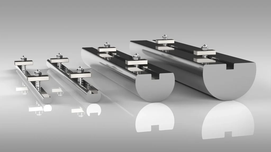
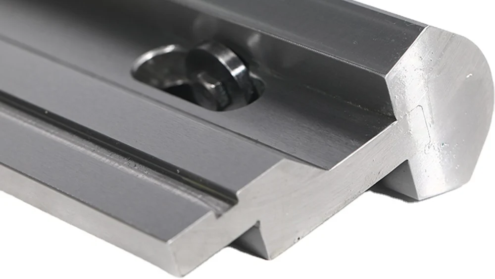
Review CAMT’s press brake radius tooling when the required radius or profile cannot be controlled reliably with a standard air-bending setup. Send the complete drawing and machine/tool interface data rather than only the requested radius.
How Should You Measure and Validate the Finished Radius?
Measure the radius after the part has unloaded, not while it remains under pressure. Use a calibrated radius gauge, optical comparator, profile scanner or coordinate measurement method appropriate to the tolerance. Measure more than one location along a long bend because crowning, alignment, material variation and tool condition can change the profile.
Record the actual material batch, thickness, V opening, punch, ram-depth correction, angle and measured radius. Use that record to calibrate bend allowance or bend deduction. A flat-pattern formula calculates from the radius entered; it does not prove that the physical process produced that radius.
Why Does the Measured Radius Miss the Calculation?
| Symptom | Possible mechanism | What to check | Corrective direction |
|---|---|---|---|
| Radius larger than estimated | Actual V is wider, material is stronger or springback is greater | Measure V, confirm grade and inspect the released profile | Use material-specific data or an approved smaller V after load checks |
| Radius smaller or creased | V or punch tip is too narrow/sharp for the material | Check V/t, punch nose and crack/crease evidence | Use a larger safe opening or punch radius and recalculate force |
| Cracks on the outside | Radius is below the material limit or grain direction is unfavorable | Confirm grade, temper, thickness and rolling direction | Increase radius/V or change blank orientation |
| Radius varies along the bend | Crowning, alignment, wear or material variation | Measure angle/radius along the length and inspect seating | Correct alignment/crowning and validate the material batch |
| Large radius is not circular | Material separates from an oversized punch during forming | Inspect contact behavior and compare with large-radius guidance | Use an engineered V/punch relationship or staged forming |
| Flat pattern is consistently wrong | Programmed radius/K-factor does not match the produced bend | Measure real radius and bend deduction from test coupons | Update the material/tooling bend database |
Frequently Asked Questions
What determines the inside bend radius in press brake air bending?
The V-die opening, material properties and bend angle are the main influences. For ordinary mild steel near 90 degrees, Ri ≈ 0.16V is a useful starting estimate, but the selected manufacturer’s chart and a controlled trial bend should confirm it.
Is the inside bend radius the same as the punch-tip radius?
Not usually in air bending. The sheet floats over the V and forms a natural radius. The punch tip must still be compatible, while bottoming, coining and dedicated radius forming give tool geometry a stronger direct role.
How do I calculate V opening from a required radius?
For the stated mild-steel air-bending baseline, use V ≈ Ri ÷ 0.16. Round to an available die, recalculate the estimated radius, then check minimum flange, force, material formability and tool capacity.
Can I use Ri = 0.16V for stainless steel or aluminum?
Do not assume so. Different grades, tempers and strength levels can produce different natural radii and springback. Use material-specific manufacturer data and verify the actual batch.
Does a smaller V opening always make a better tight radius?
No. It can reduce the natural radius, but it also increases force, pressure, marking, creasing and cracking risk. The opening must satisfy material, flange, load and tool-life requirements together.
When should I use a press brake radius tool?
Use dedicated radius tooling when a large or tightly controlled radius cannot be produced reliably with a practical standard V opening, or when profile tolerance, finish or repeatability requires an engineered forming surface.
How accurate is a calculated press brake bend radius?
It is a setup estimate when material, angle, method and V definition match the source. Tight-tolerance work requires a trial bend, measurement after unloading and calibrated bend data for the actual material and tooling.
How Should You Calculate and Confirm Press Brake Bend Radius?
Start by identifying the radius term and bending method. For ordinary mild-steel air bending near 90 degrees, use Ri ≈ 0.16V to shortlist an opening, then check the real die, flange, punch, material, force and capacity. Complete the process with a measured trial bend and corrected bend data.
Request a CAMT radius-tooling review.
Send Harmon Tech the part drawing, material grade and strength, thickness, rolling direction, bend angle, target radius and tolerance, flange and bend lengths, finish requirement, press brake model, clamping interface, current tooling and preferred segmentation. CAMT can review whether standard air bending or application-specific radius tooling is the better starting point.