How Do You Choose the Correct Press Brake Punch Radius?
Choose a punch tip radius by checking the bending method, material and expected inside bend radius together. For conventional air bending, estimate the natural radius produced by the material and V-die first. Then shortlist a punch nose compatible with that radius, the required finish and the tool’s rated load.
The radius printed on a part drawing describes the finished part. It is not automatically the radius to order on the punch. Reliable punch radius selection also requires the correct punch angle, body clearance, clamping interface and a measured trial bend.
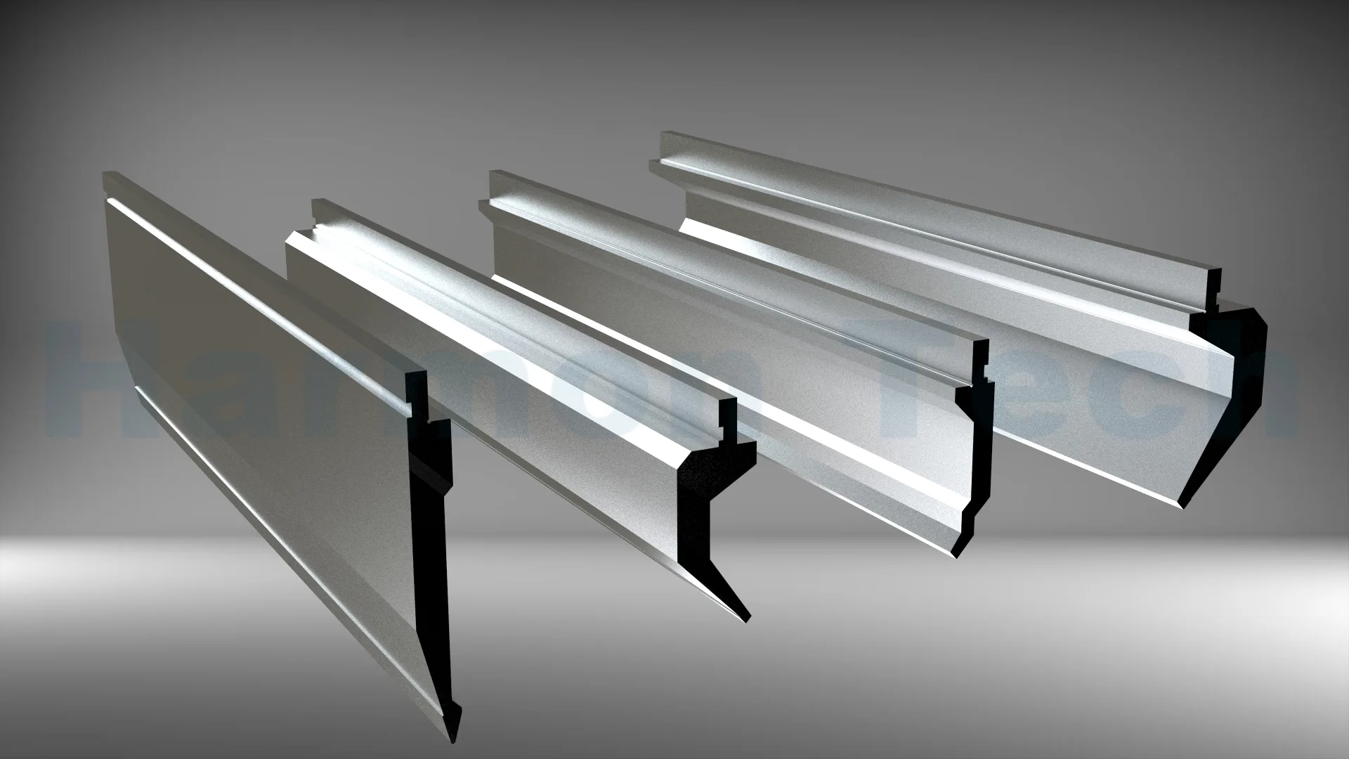
What Is the Difference Between Punch Tip Radius and Inside Bend Radius?
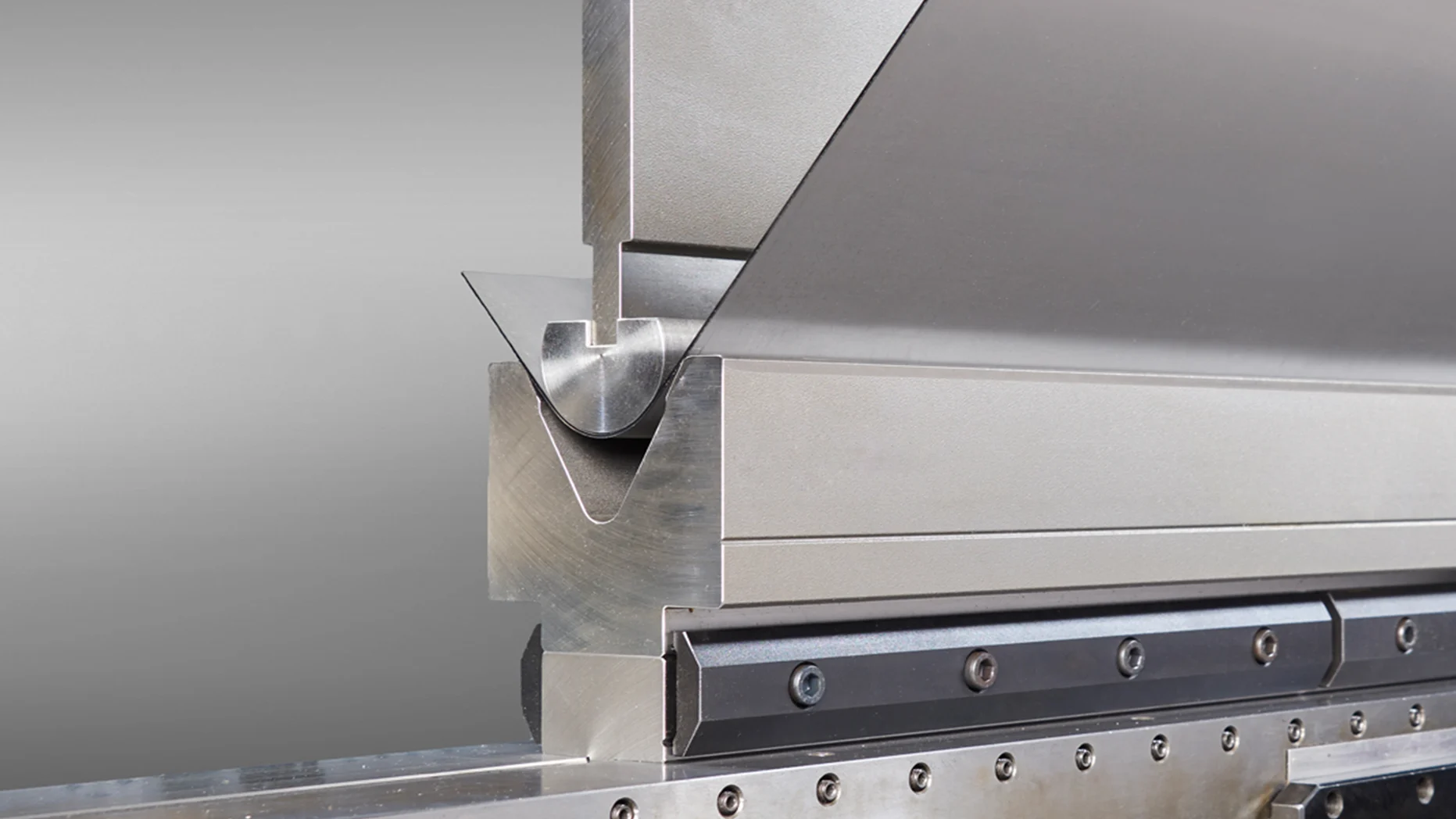
The punch tip radius, written here as Rp, is the curved nose of the upper tool. The inside bend radius, Ri, is the internal curvature of the formed sheet. Sheet thickness is t, and the lower die opening is V. Keep these four dimensions separate when reviewing drawings or entering tooling data.
In ordinary air bending, the sheet contacts the punch and the two die shoulders without being fully enclosed by the tools. The material and opening influence the curvature between those contact regions. A nominal R1 punch therefore does not establish an R1 finished part by itself.
| Parameter | Where to find it | What it tells you |
|---|---|---|
| Punch tip radius, Rp | Tool drawing or verified tool record | Nose geometry and contact condition |
| Finished inside radius, Ri | Part drawing and inspection requirement | Required part geometry after unloading |
| Material thickness, t | Drawing and measured stock | Input to bending feasibility and force |
| V-die opening, V | Die drawing or manufacturer definition | Support spacing used in the selected bending model |
Which Punch Radius Selection Rule Applies to Air Bending?
WILA’s punch tip radius guidance recommends a nose close to the expected natural radius without exceeding it. A much smaller tip can indent the bend line; an oversized nose can change how the sheet wraps around or separates from the tool. This is a starting principle for conventional air bending, not a prohibition on purpose-designed radius tooling.
Screen a candidate against the actual job rather than applying a universal radius-to-thickness multiplier. A punch that gives acceptable parts in one material batch may produce visible indentation in another. A tool that clears an open bracket may collide with the return flange of a box.
Separate three questions: Will the material tolerate the required bend? Does the punch suit the intended contact geometry? Can the complete assembly carry the load? Answering only the first two is insufficient for production selection.
How Do the V Opening and Material Affect the Choice?
For a preliminary mild-steel air-bending estimate, Bystronic’s tooling selection rules relate the inside radius to approximately 16% of the opening. They also describe an opening of about eight times sheet thickness and a minimum flange of approximately 77% of the opening as useful starting rules.
Estimated Ri ≈ 0.16 × V
These estimates help screen a tooling combination. They do not establish a guaranteed radius tolerance, a universal material minimum or a tool load rating. Use consistent units, check the opening definition on the die drawing, and use the material supplier’s bending recommendations where available.
If you narrow the opening to reduce the expected radius, recalculate bending force. If you widen it to reduce force, recheck the flange support and resulting radius. Selecting the punch before resolving those constraints can leave you with a technically suitable nose on an unsuitable setup.
| Material situation | What to confirm | Selection consequence |
|---|---|---|
| Ordinary mild steel | Grade, strength, thickness and bend direction | Use the estimate to shortlist tools, then measure a trial |
| Stainless steel | Exact grade, condition and finish requirement | Check springback, force and contact marking for that stock |
| Aluminum | Alloy, temper and supplier minimum bend recommendation | Do not transfer a steel setup without checking cracking and surface damage |
| High-strength sheet or plate | Supplier bending limits and orientation requirements | Review radius, opening and capacity as a complete application |
| Coated or cosmetic sheet | Acceptable impressions and coating damage | Approve the contact surface and trial finish as well as dimensions |
How Should You Compare Available Punch Radii?
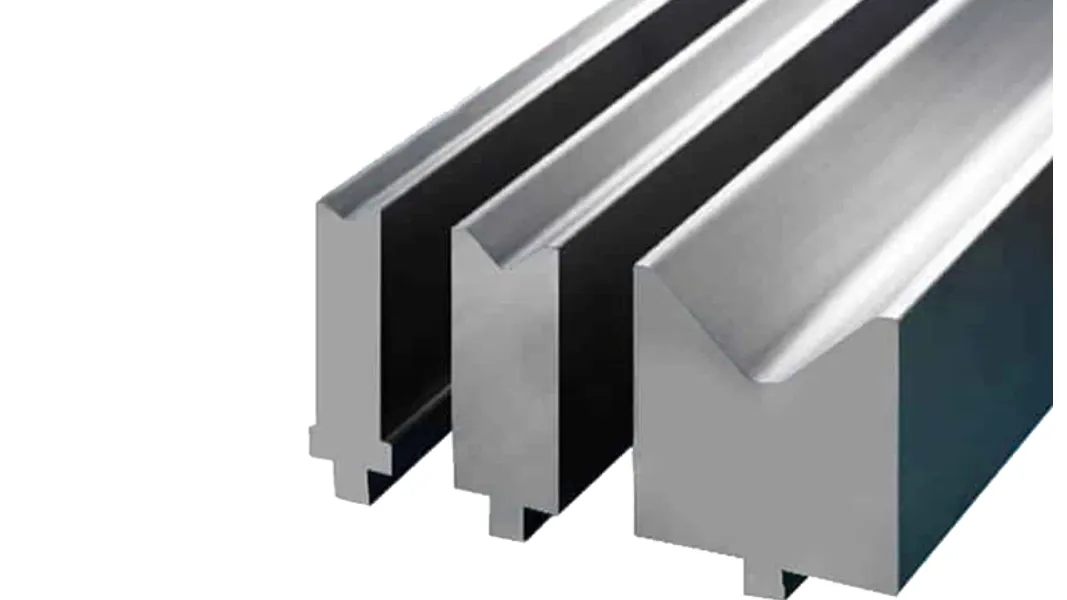
Make a shortlist from the tools you can actually obtain. Record the nose radius, angle, working height, profile, working length and load restriction for each candidate. Catalog labels alone are not enough: two tools with the same nose radius can have very different clearance and loading limits.
Use a larger compatible nose when a smaller one produces unacceptable local contact effects, but recheck the entire bend geometry after changing tools. If the natural radius is incompatible with the drawing, solve that process mismatch first. Choosing a different nose is not a reliable substitute for selecting the correct die and forming method.
| Candidate condition | What to investigate | Next action |
|---|---|---|
| Noticeably sharper than the estimated bend | Indentation, surface specification and local deformation | Compare a closer-radius candidate and inspect a trial |
| Near the estimated bend radius | Material variability and actual formed profile | Keep on the shortlist if clearance and load checks pass |
| Above the estimated natural radius | Whether the application is deliberately radius forming | Reassess the matched punch-and-die process |
| Correct radius but unsuitable body | Return-flange collision or insufficient tool strength | Choose a different rated profile with the required nose |
Worked Example: Selecting a Punch for 2 mm Mild Steel
This is an illustrative screening exercise, not an approved machine setup. Assume ordinary mild steel with tensile strength around 450 MPa, 2.0 mm measured thickness, a 500 mm bend length, a finished 90° air bend, a nominal 2.5 mm inside radius and a 20 mm flange. Confirm the actual grade and drawing tolerances before production.
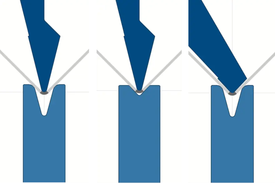
1. Establish the die candidate
Using an eight-times-thickness starting point gives V = 8 × 2 = 16 mm. The estimated inside radius is Ri ≈ 0.16 × 16 = 2.56 mm. That is close enough to the nominal target to investigate, but whether it meets the drawing depends on the specified tolerance and actual trial.
The preliminary flange screen is 0.77 × 16 = 12.32 mm. The proposed 20 mm flange is longer than that estimate. Confirm the flange measurement convention, real shoulder geometry and support through the stroke.
2. Compare candidate noses
| Punch nose | Comparison with estimated Ri = 2.56 mm | Screening decision |
|---|---|---|
| R0.8 mm | Much smaller | Lower priority; investigate bend-line indentation |
| R2.0 mm | Smaller, relatively close | Reasonable candidate for trial evaluation |
| R2.5 mm | Very close | Candidate only after checking actual material behavior and tool geometry |
| R4.0 mm | Larger | Do not treat as an equivalent conventional air-bending substitution |
3. Complete the tool and capacity checks
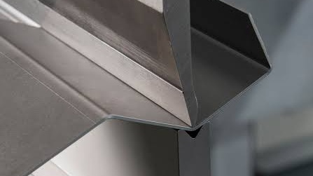
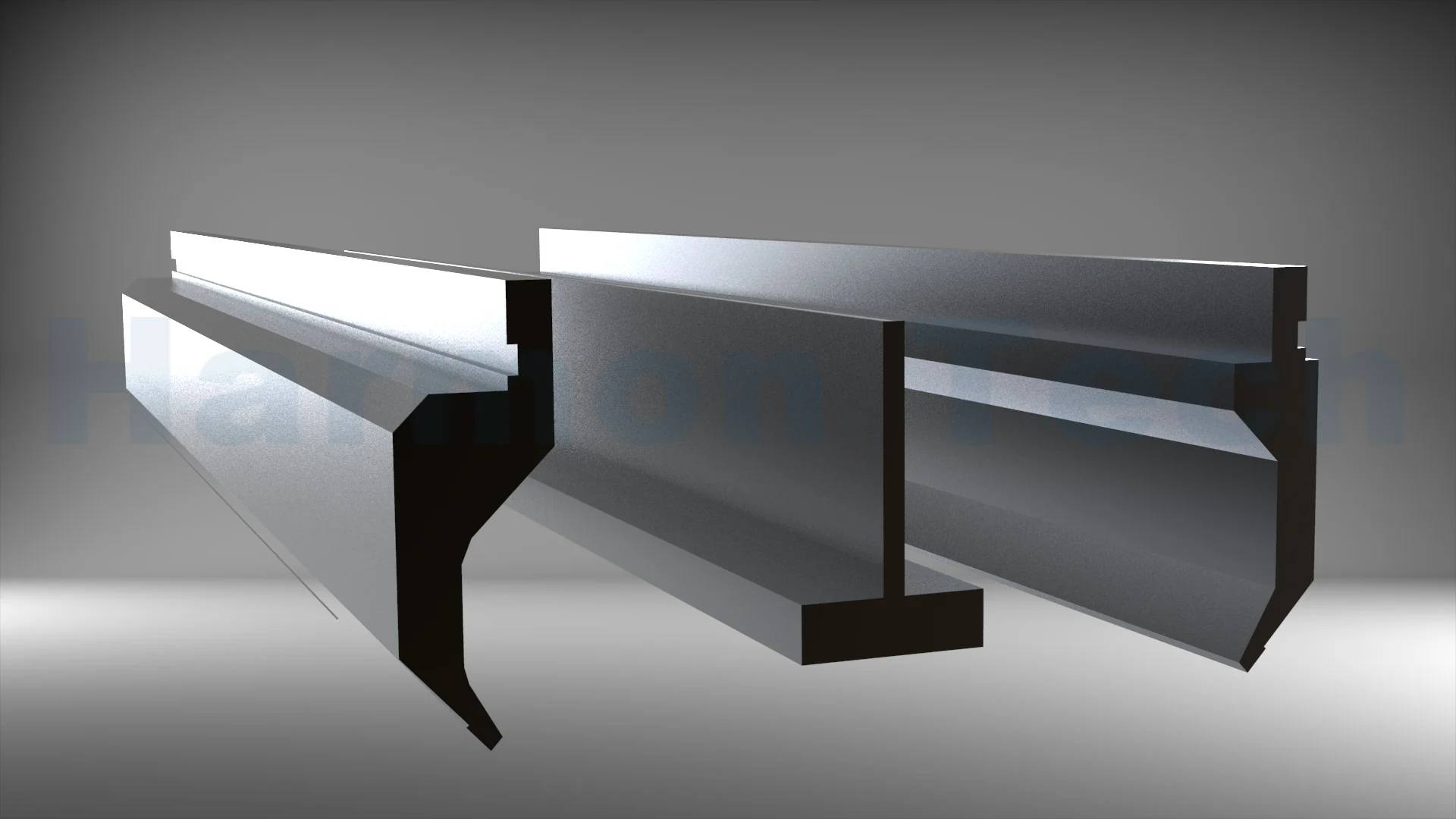
Start with a straight profile only if the part and bend sequence permit it. Select punch and die angles that allow the required overbend without unintended bottoming. Confirm compatible working heights, clamping and clearance over the full stroke.
Read the required force from an approved air-bending chart or validated calculation using the confirmed material strength, 2 mm thickness, 16 mm opening and 500 mm length. Compare it with the permitted loading of the machine, punch, die, holders and clamps. No tonnage approval can be inferred from the radius calculation alone.
4. Choose from measured results
Trial the shortlisted setup on representative stock. Measure the unloaded angle and radius, check flange dimensions and inspect the bend line. Record the exact tool IDs, material lot and measured thickness. Select the candidate that meets the drawing and finish requirements within the approved operating limits.
When Do You Need a Press Brake Radius Punch?
A press brake radius punch is appropriate when the job deliberately requires a broad curved forming surface. That is a separate tooling application from selecting the nose on an ordinary straight or gooseneck punch. Review the required radius-to-thickness relationship, support geometry, springback and profile tolerance with the tooling supplier.
For a large curved panel, compare a dedicated radius tool with an approved multi-step forming process. The useful comparison is the resulting surface, profile tolerance, number of operations and available clearance. A smoother-looking tool does not by itself establish the final released shape.
Bottoming and coining also require their own matched-tool assessment. Do not transfer an air-bending selection rule or force estimate to those methods. The extent of tool contact and the load requirement change with the process.
What Else Must You Check Before Ordering?
CONIC’s tool-selection guidance emphasizes checking interference with tool cross-sections and validating the selection by trial bending. Apply that check to every forming step, including the position of previously bent flanges and the removal of the finished part.
Confirm the tang dimensions, clamp type, retention arrangement, orientation, working height and section lengths. “Amada system” is a product category, not proof that every tool fits every holder. Compare the dimensioned tool and clamp drawings before ordering.
For the relevant product range, review CAMT’s Amada-system punches and request the drawing and rated load for the exact profile. For the broader die, material and machine decisions, use the guide on how to choose press brake tooling.
Also specify the usable bending length and segmentation. A short tool section or relieved gooseneck may have restrictions that cannot be inferred from the rating of a different tool. Keep the machine and every load-bearing component within its manufacturer’s limits.
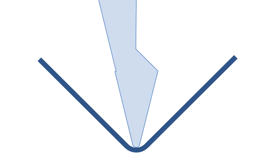
How Do You Diagnose an Unsuitable Bending Punch Radius?
| Symptom | Possible cause to verify | Useful response |
|---|---|---|
| Visible indentation along the inside bend | Nose geometry, damaged contact surface or excessive local loading | Inspect the tool and compare a compatible alternative |
| Cracking at the bend | Material bendability, orientation, edge condition or overly tight forming | Check supplier limits and revise the process before another run |
| Radius differs from the drawing | Wrong opening, material model or bending method | Measure the actual setup before changing the punch |
| Angle varies along the length | Seating, alignment, material variation or crowning | Check the full setup rather than attributing everything to Rp |
| Correct geometry but unacceptable marking | Contact finish, contamination or protective-layer effects | Approve a representative cosmetic sample |
Frequently Asked Questions
Is the punch tip radius the same as the finished inside radius?
Not necessarily. In ordinary air bending, the material, V opening and angle influence the natural radius. Record the tool radius and finished part radius as separate dimensions.
Can I choose punch radius from thickness alone?
Thickness helps screen a tool, but it does not resolve material bendability, V opening, process, finish, clearance or capacity. Check those inputs before approving the selection.
Will a sharper punch always produce a smaller inside radius?
No. A sharper nose can change the local contact condition without delivering the intended overall bend profile. Recheck the die and process when the measured radius is too large.
Can one punch radius handle steel, stainless steel and aluminum?
It may serve several approved applications, but each grade, temper, thickness and finish requirement needs validation. A successful setup in one material is not proof of suitability in another.
When should I select a dedicated radius punch?
Consider one when the part requires a broad controlled curvature that the ordinary tooling combination does not reliably deliver. Review the matching lower tool, springback and part clearance.
Does an Amada-system punch fit every Amada-style clamp?
Do not assume compatibility from the name. Compare the actual tang, holder, retention feature, orientation and working-height drawings, and confirm the permitted loading.
What should I measure during a punch selection trial?
Measure the released angle, inside profile and flange dimensions, then inspect the surface and any cracking. Record material lot, thickness, tool IDs and approved settings for repeatability.
Choose the Punch as Part of a Complete Setup
The correct punch tip radius is the one that supports the required part geometry in a verified tooling combination. Start with the drawing and material, establish the die and bending method, compare realistic punch candidates, then approve the result through inspection.
Ask Harmon Tech / CAMT to review your tooling requirement. Send the part drawing, material grade and condition, thickness, target angle and inside radius, bend length, minimum flange, press brake model, clamp drawing and segmentation requirements. Include the surface specification so the recommendation covers finish as well as geometry.